Fuel injection valve for internal combustion engines

a technology for internal combustion engines and fuel injection valves, which is applied in the direction of fuel injection apparatus, feeding system, spraying apparatus, etc., can solve the problems of not being able to determine, the hydraulically effective seat diameter, and the increase in the area acting in the opening direction

Inactive Publication Date: 2002-11-07
ROBERT BOSCH GMBH
View PDF8 Cites 5 Cited by
  • Summary
  • Abstract
  • Description
  • Claims
  • Application Information

AI Technical Summary

Problems solved by technology

In the known valve members, however, it is not possible to determine beforehand how much the hydraulically effective seat diamete

Method used


Image

  • Fuel injection valve for internal combustion engines
  • Fuel injection valve for internal combustion engines
  • Fuel injection valve for internal combustion engines

Examples


Embodiment Construction

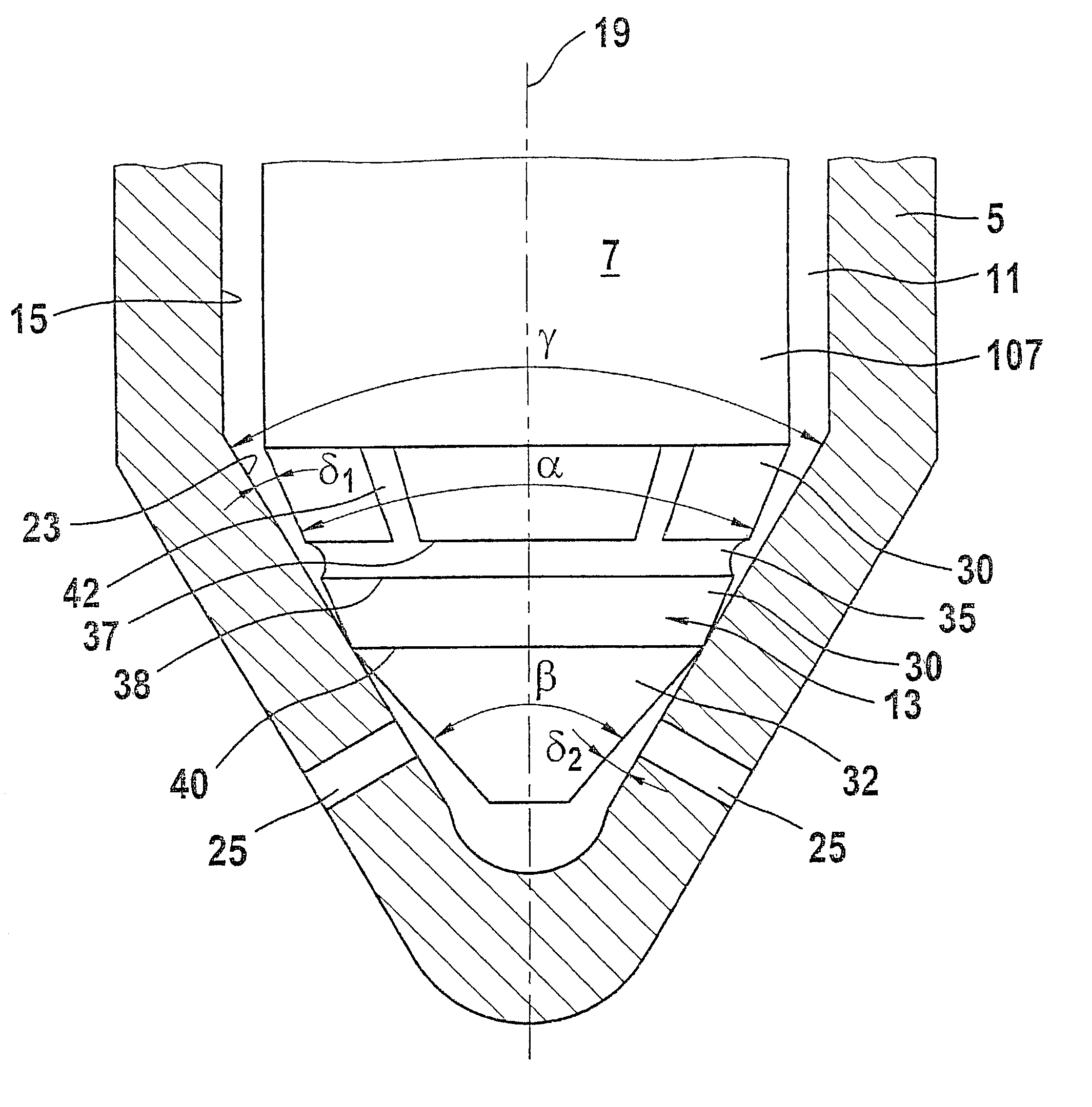
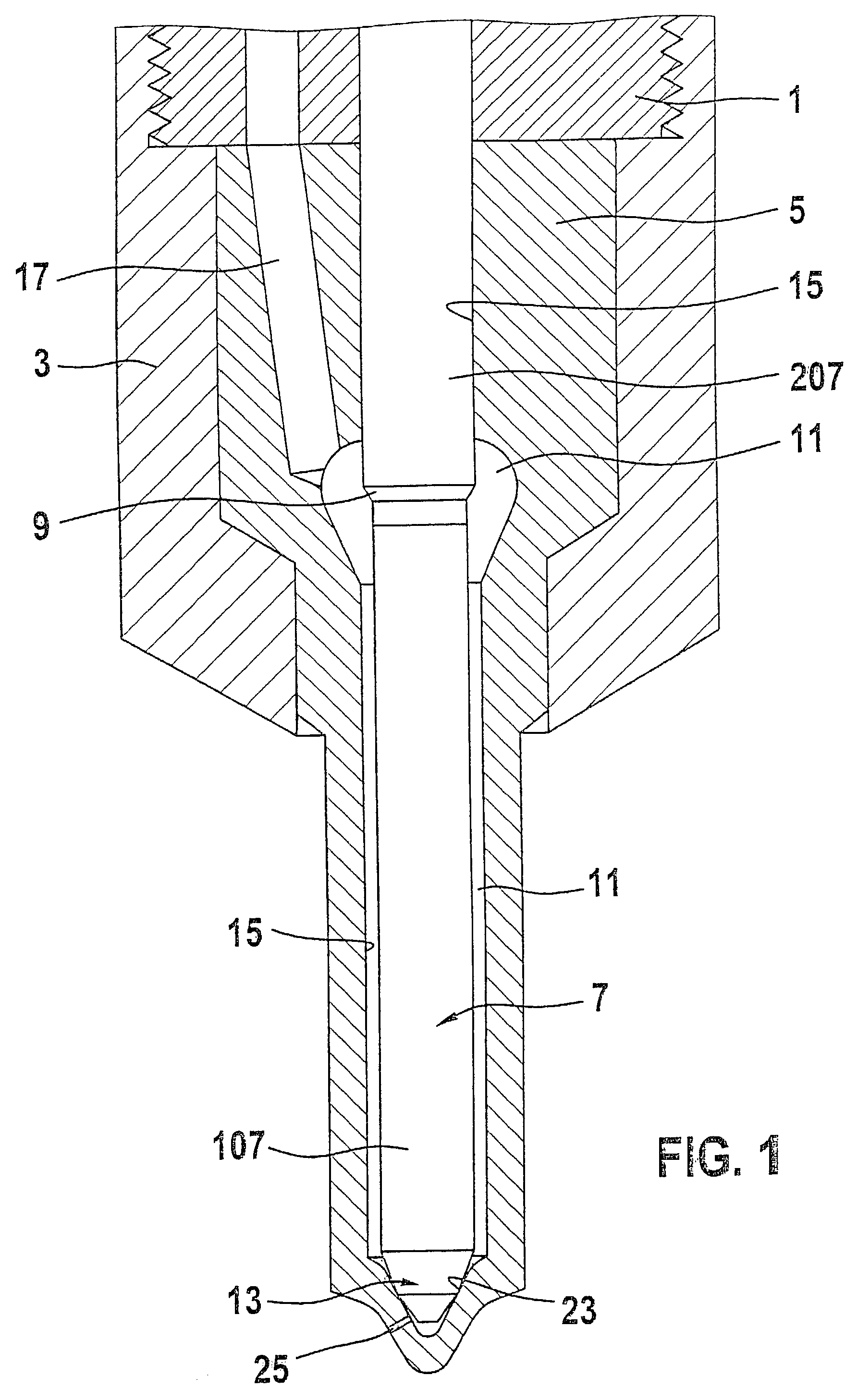
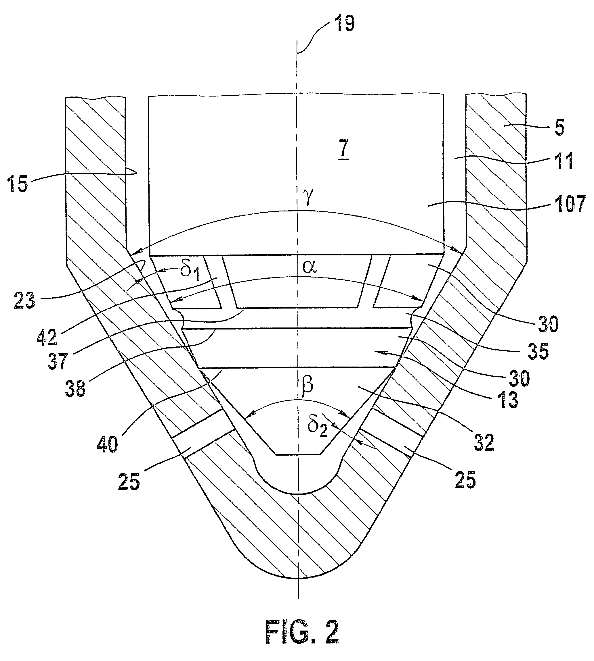
[0010] In FIG. 1, a fuel injection valve for internal combustion engines is shown in partial longitudinal section. A valve body 5 is braced against a valve holding body 1 by means of a fastening element 3; these three elements together form a nozzle holder combination, which in the installed position is disposed in a receiving bore, not shown in the drawing, of an internal combustion engine. A bore 15 is embodied as a blind bore in the valve body 5, and its bottom face is oriented toward the combustion chamber. On the bottom face of the bore 15, a conical valve seat 23 with a cone angle y is formed, along with at least one injection port 25, which connects the bore 15 to the combustion chamber. Disposed in the bore 15 is a pistonlike valve member 7, which has a longitudinal axis 19 and which with a guide portion 207 remote from the combustion chamber is guided in the bore 15 and is thus axially movable. Toward the combustion chamber, the valve member 7 narrows, forming a pressure sh...


PUM


Abstract

A fuel injection valve having a valve body (5), in which a pistonlike valve member (7) is guided longitudinally displaceably in a bore (15) embodied as a blind bore. A conical valve seat (23) and at least one injection port (25) are embodied on the bottom face of the bore (15), and the injection port connects a pressure chamber (11), formed between the portion (107) of the valve member (7) toward the combustion chamber and the bore (15), with the combustion chamber. On the end toward the combustion chamber of the valve member (7), there is a valve member tip (13), on which a first conical face (30), adjacent to the valve member (7), and a second conical face (32), disposed on the combustion chamber side of the first conical face, are embodied. The cone angle (alpha) of the first conical face (30) is less, and the cone angle (beta) of the second conical face (32) is greater, than the cone angle (gamma) of the valve seat (23), so that a sealing edge (40) is formed at the transition of the two conical faces (30, 32). Embodied on the first conical face (30) is an encompassing annular groove (35), which limits an increase in the hydraulically effective seat diameter caused by the plastic deformation of the sealing edge (40) and the valve seat (23) to a precisely defined extent (FIG. 2).

Description

PRIOR ART[0001] The invention is based on a fuel injection valve for internal combustion engines as generically defined by the preamble to claim 1. One such fuel injection valve is known from German Patent Disclosure DE 196 34 933 A1. On the end toward the combustion chamber of the valve member, there is a valve member tip with two conical faces. A first conical face is adjacent to the valve member shaft and has an opening angle that is less than that of the conical valve seat. The first conical face is adjoined toward the combustion chamber by a second conical face, whose opening angle is greater than that of the valve seat, so that at the transition of the two conical faces, a sealing edge is formed, which in the closing position of the valve member comes to rest on the valve seat as a result of a closing force acting on the valve member.[0002] The opening stroke motion of the valve member is exerted by the hydraulic force of the fuel in the pressure chamber, which in the closing ...

Claims


Application Information

Patent Timeline
IPC IPC(8): F02M61/04F02M61/10F02M61/18F02M63/00
CPCF02M61/047F02M2200/30F02M61/1873F02M61/1866F02M61/18
Inventor HOCKENBERGER, AXEL
Owner ROBERT BOSCH GMBH
Why Eureka
Try Eureka