

Suspension device for a bed or seat base of the multielement type
a multi-element, suspension device technology, applied in the direction of seating furniture, mattresses, applications, etc., can solve the problems of uneven hardness and provide leakage tightness around the holes, and achieve the effect of convenient positioning of the top pla
- Summary
- Abstract
- Description
- Claims
- Application Information
AI Technical Summary
Benefits of technology
Problems solved by technology
Method used
Image

Examples
second embodiment
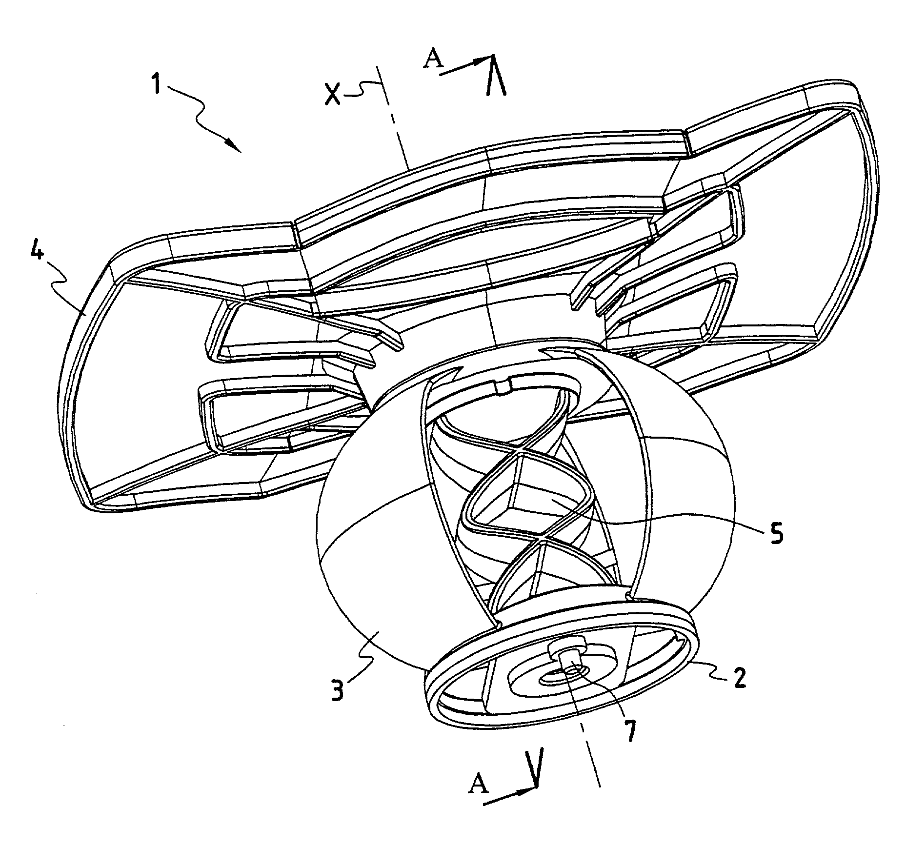
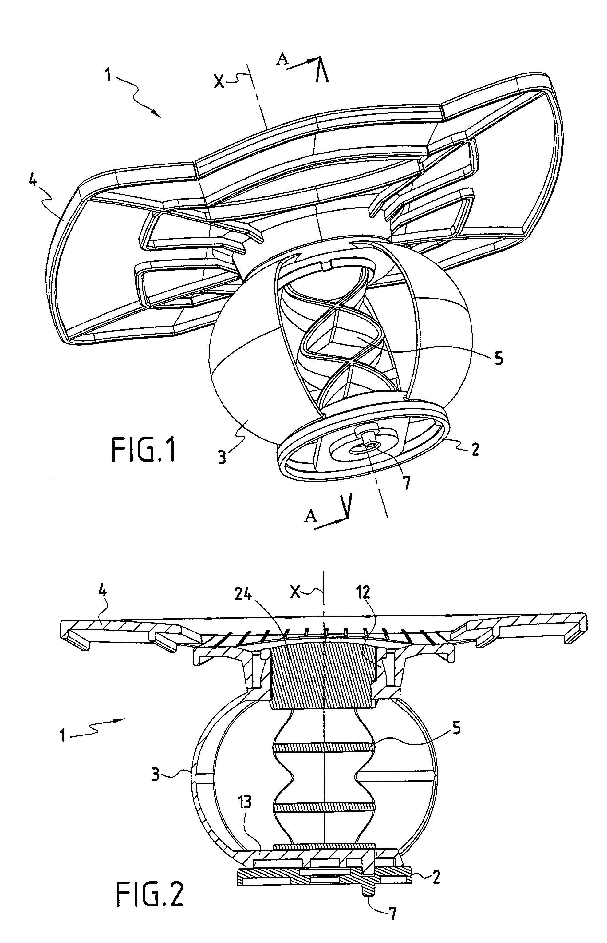
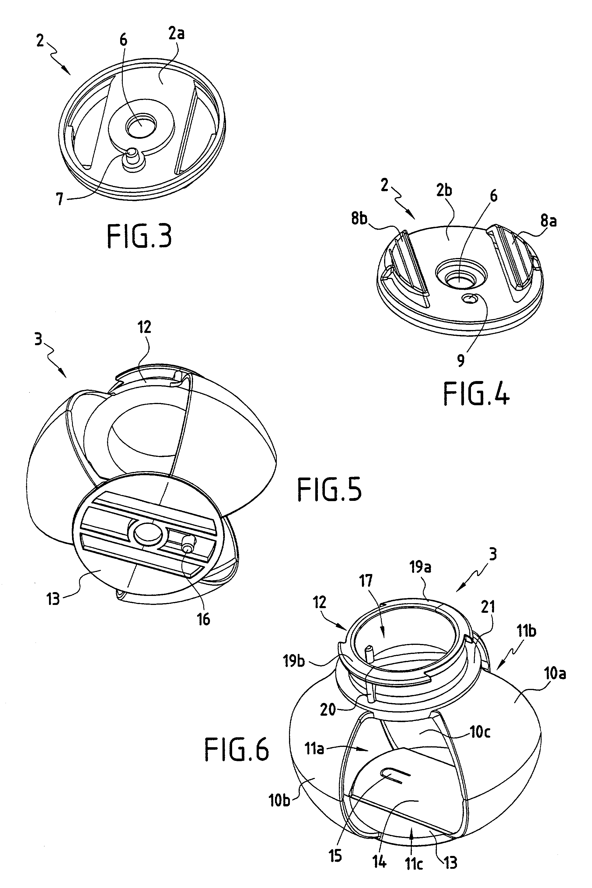
[0063] FIGS. 28 to 31 show the invention. This suspension device 1 likewise comprises a foot 2 as shown in FIG. 30, a suspension structure 3 of spherical shape as shown in FIG. 29, and a top plate of square shape as shown in FIG. 31. The suspension structure 3 presents a head 12 for fixing the top plate 4, which head has a cylindrical wall terminated by an annular flange 70 for retaining resilient fingers 71 provided on the inside wall of the central orifice 18 in the top plate 4. The inside wall of this orifice 18 also has notches 72 suitable for being placed astride opposite radial ribs 73a and 73b formed in the top portion of the sphere at the bottom of the head 12 so as to prevent the top plate 4 turning about the axis X relative to the suspension structure 3 after they have been assembled together.
first embodiment
[0064] In its bottom hemisphere, the suspension structure 3 has three sectors 10a, 10b, and 10c which are separated by slots 11a, 11b, and 11c of small circumferential extent. Compared with the first embodiment, the suspension structure 3 does not have a bottom member 13 in its bottom zone. The bottom ends of the sectors 10a, 10b, and 10c are thus free. Beneath its bottom face, the foot 2 has side walls 52a and 52b suitable for receiving a slat between them, and it has a tenon 54 for fixing it to the slat, while on its top face 2b it has an upwardly flared neck 75 made up of three elements that are regularly spaced apart around the axis of the foot 2, each presenting an upwardly-extending rib 76 on its outside face of circumferential size matching the width of a slot 11a, 11b, or 11c. When the bottom ends of the sectors 10a, 10b, and 10c are urged elastically outwards, it is possible to fit the bottom portion of the suspension structure 3 over the neck 75 so that the ribs 76 are rec...
third embodiment
[0065] FIG. 32 shows the invention. In this case the foot 2 and the suspension structure are made as a single piece. The foot 2 presents two tenons 80a and 80b on its bottom face 2a enabling it to be fastened quickly in holes formed in a slat, and optionally an abutment 81 which bears against a side face of the slat.
[0066] FIG. 33 shows a cap 90 having two tabs 91a and 91b suitable for sliding into the gap between the flange portions 19a and 19b of the head 12 and the projections 22 of the top plate 4 in the first embodiment of the invention as described above after the top plate 4 has been turned through one-fourth of a turn and non-return snap-fastening has taken place. The cap 90 can be made of overmolded cloth or as a piece of plastics material worked by thermocompression. It can carry attractive markings or decoration.
[0067] FIGS. 34 to 38 show an eighth variant of the suspension device as described with reference to FIGS. 1 to 10. The foot 2 differs from that shown in FIGS. 3 ...
PUM
| Property | Measurement | Unit |
|---|---|---|
| Shape | aaaaa | aaaaa |
| Symmetry | aaaaa | aaaaa |
Abstract
Description
Claims
Application Information