
Cutter blade sharpener and method

a cutter blade and sharpener technology, applied in the field of cutter blade sharpeners, can solve the problems of uneven fashion, constant wear of cutter blades, cost of labor and equipment, etc., and achieve the effect of uniform sharpening and convenient operation

Inactive Publication Date: 2002-11-21
COBBLER LARRY R
View PDF0 Cites 9 Cited by
  • Summary
  • Abstract
  • Description
  • Claims
  • Application Information

AI Technical Summary

Benefits of technology

[0003] With recent increased costs of labor and equipment in the tree harvesting industry, maintenance of circular cutters having a plurality of cutter blades are a source of concern. It is not prudent to use a circular cutter until it is completely worn and then discard it. Also, it is now not prudent or economical to hand grind each cutter blade to attempt to restore it to its original sharpness. As a result there has become a need for a powered cutter blade sharpener which is fast and which can be efficiently operated for uniform sharpening among the individual cutter blades to keep the circular cutter in balance.
[0004] Thus, with the aforesaid problems and disadvantages of discarding and replacing cutter blades, the present invention was conceived and one of its objectives is to provide a cutter blade sharpener which can be readily operated to provide uniform sharpening of cutter blades several times before discarding.
[0005] It is a further objective of the present invention to provide a method of sharpening cutter blades which allows cutter blades to be reused again and again.
[0006] It is still another objective of the present invention to provide a cutter blade sharpener which will allow all the blades of the circular cutter to be sharpened to the same degree and depth.
[0009] It is another objective of the present invention to provide a cutter blade sharpener which includes a stop to limit the movement of the slide table to ensure uniform sharpening from blade to blade.
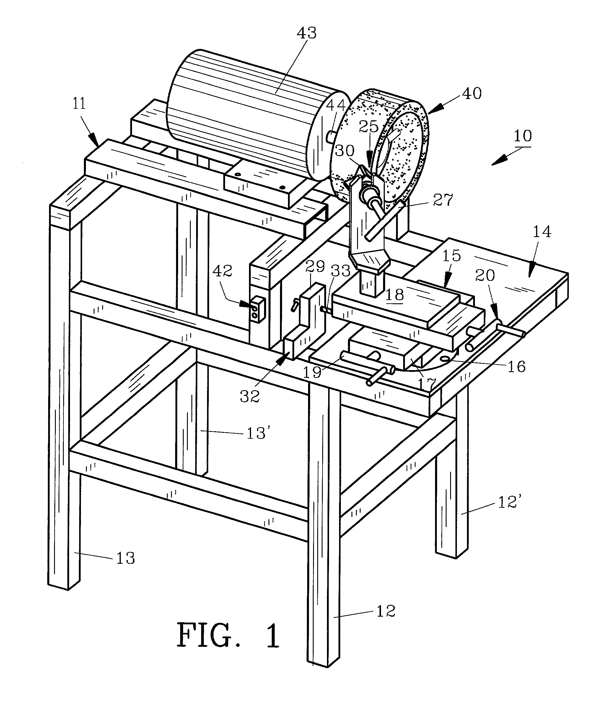
[0012] The first cutter blade selected for sharpening, being the most worn, is attached to a threaded handle. By placing the threaded handle in the slot and tightening the same, the cutter blade is prevented from movement during sharpening. A V-shaped guide is positioned below the slot on the support arm to prevent the cutter blade from rotating as it is tightened onto the handle and during grinding. An adjustable stop attached to the frame terminates the rear longitudinal movement of the table top. By thus adjusting the stop, an exact rear position is provided whereby each of the four pairs of edges of the cutter blades are sharpened to the same degree or depth. Once the first edge is sharpened, the cutter blade is moved away from the grinding wheel and the cutter blade is loosened on the handle to allow the blade to rotate 90.degree.. The rotated cutter blade is retightened and the second edge of the cutter blade is then sharpened by rotating the table base handle and table top handle to bring the cutter blade into contact with the grinding wheel. After all four edges of the cutter blade have been sharpened thusly, the first cutter blade is removed and replaced on the circular cutter while another cutter blade is attached to the arm support as aforedescribed and the sharpening method starts anew. The stop, having been adjusted for the most worn blade, remains in position so that all cutter blades are sharpened to the same depth. Uniformly sharpened cutter blades maintain balance for the circular cutter as it spins during cutting. A relatively large number of blades can be sharpened quickly and efficiently by relatively unskilled personnel by using the method and sharpener thus described.

Problems solved by technology

The cutter blades regularly wear, sometimes in an uneven fashion and must be removed and discarded.
With recent increased costs of labor and equipment in the tree harvesting industry, maintenance of circular cutters having a plurality of cutter blades are a source of concern.
It is not prudent to use a circular cutter until it is completely worn and then discard it.
Also, it is now not prudent or economical to hand grind each cutter blade to attempt to restore it to its original sharpness.

Method used


Image

  • Cutter blade sharpener and method
  • Cutter blade sharpener and method
  • Cutter blade sharpener and method

Examples


Embodiment Construction

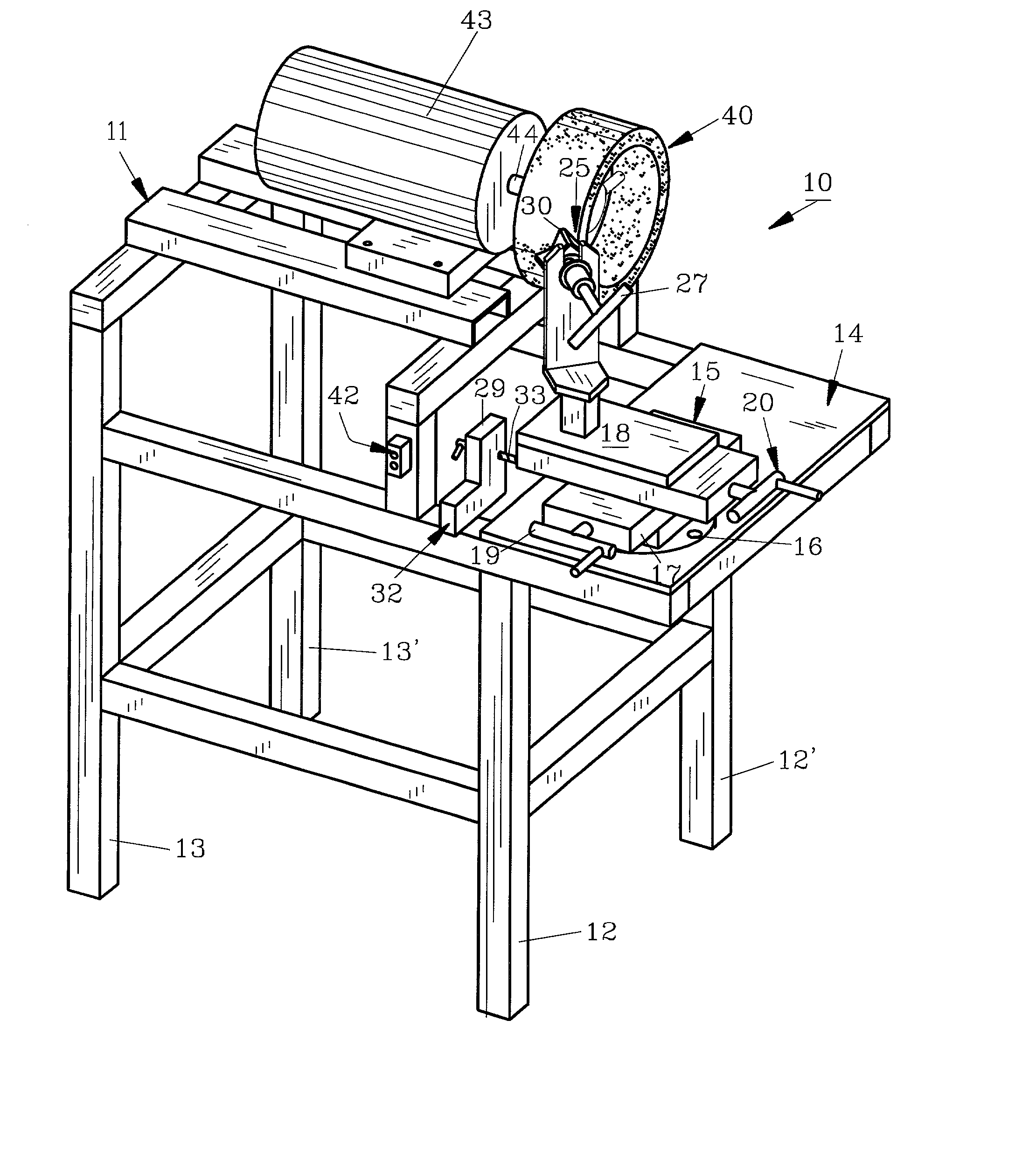
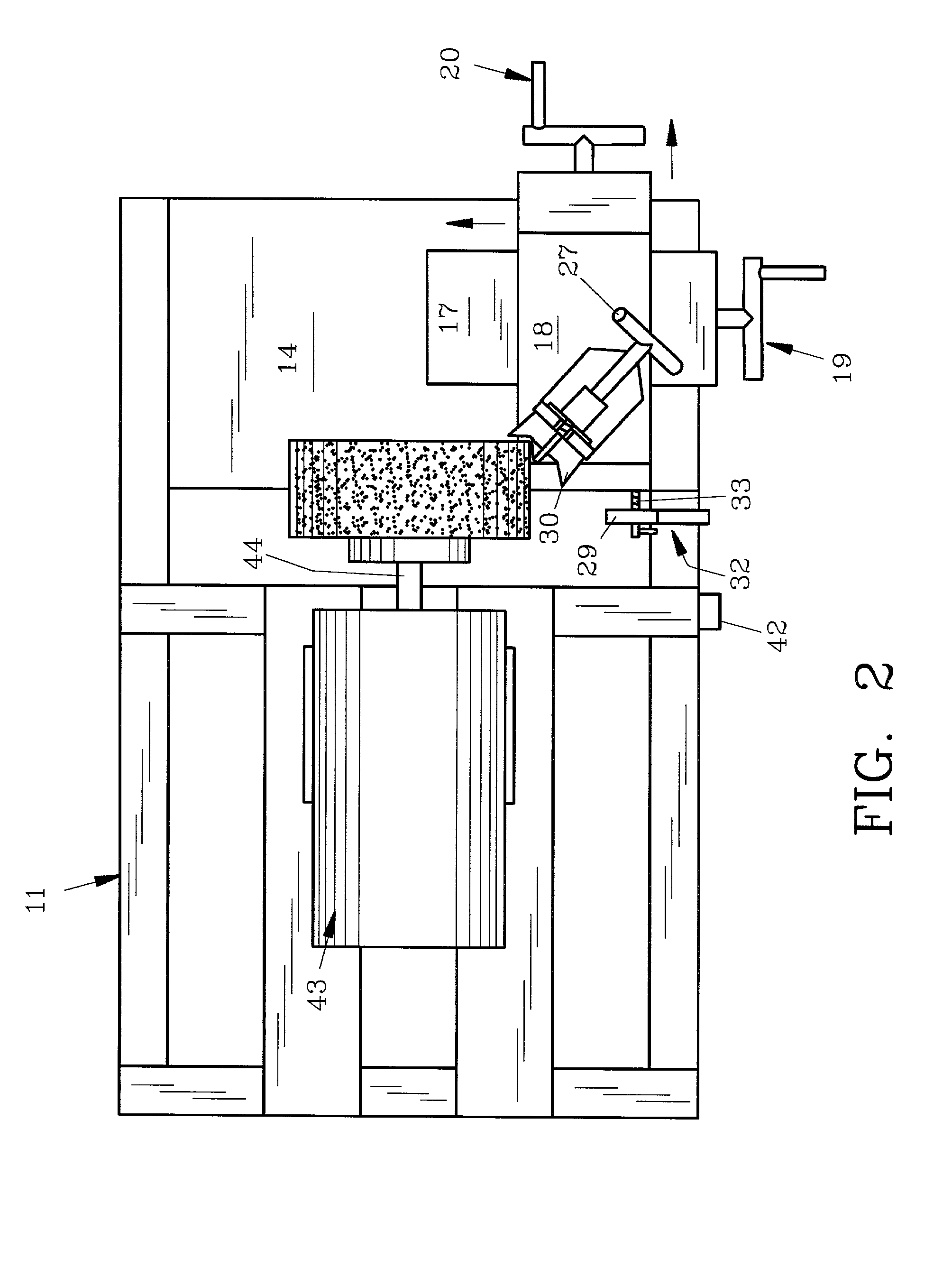
[0018] For a better understanding of the invention and its method of operation, turning now to the drawings, FIG. 1 illustrates preferred cutter blade sharpener 10 having frame 11 preferably formed from tubular steel. Frame 11 includes front legs 12, 12' and rear legs 13, 13'. Rigidly positioned on tubular frame 11 is shelf 14 to which slide table 15 is mounted. Slide table 15 is preferably a conventional compound or bi-directional milling table as sold by Enco Manufacturing of 135 South LaSalle, Chicago, Ill. 60674. Other manufacturers of such slide tables include Penn Tool Company, 1776 Springfield Avenue, Maplewood, N.J. 07040. Slide table 15 is mounted to shelf 14 as by bolts 16 (only one shown in FIG. 1) and includes table base 17 and table top 18. Table base 17 is movable laterally on frame 11 by turning crank handle 19 whereas table top 18 is movable longitudinally on frame 11 by turning crank handle 20 as seen by the arrows in FIG. 2. As would be understood, table base 17 an...


PUM

PropertyMeasurementUnit
Timeaaaaaaaaaa

Abstract

A cutter blade sharpener and method allows for quick, easy and uniform sharpening of tree felling head circular cutters. Each cutter blade is individually removed from the circular cutter and is positioned on the sharpener, one at a time whereby the cutter blades are then ground in uniform fashion. The sharpener includes a tubular frame having a slide table mounted thereon for both lateral and longitudinal movement of the cutter blade proximate the grinding wheel.

Description

[0001] The invention herein pertains to blade sharpeners and particularly for sharpeners for cutter blades as are used with tree felling heads.DESCRIPTION OF THE PRIOR ART AND OBJECTIVES OF THE INVENTION[0002] Many standard tree felling heads utilize circular cutters which turn at high rates of speed for felling trees. Such circular cutters commonly have eighteen cutter blades, each with four cutting edges located along the periphery of the circular cutter. The cutter blades regularly wear, sometimes in an uneven fashion and must be removed and discarded. The standard practice is to remove the blades from the circular cutter and replace them with new cutter blades.[0003] With recent increased costs of labor and equipment in the tree harvesting industry, maintenance of circular cutters having a plurality of cutter blades are a source of concern. It is not prudent to use a circular cutter until it is completely worn and then discard it. Also, it is now not prudent or economical to han...

Claims


Application Information

Patent Timeline
IPC IPC(8): B24B3/36B24B41/06
CPCB24B41/065B24B3/36
Inventor COBBLER, LARRY R.
Owner COBBLER LARRY R
Learn More