Video display apparatus, audio mixing apparatus, video-audio output apparatus and video-audio synchronizing method
a technology of video display and audio mixing, which is applied in the direction of two-way working systems, instruments, television systems, etc., can solve the problems of a delay time of 30 to 60 msec in the display driving circui
- Summary
- Abstract
- Description
- Claims
- Application Information
AI Technical Summary
Problems solved by technology
Method used
Image
Examples
first embodiment
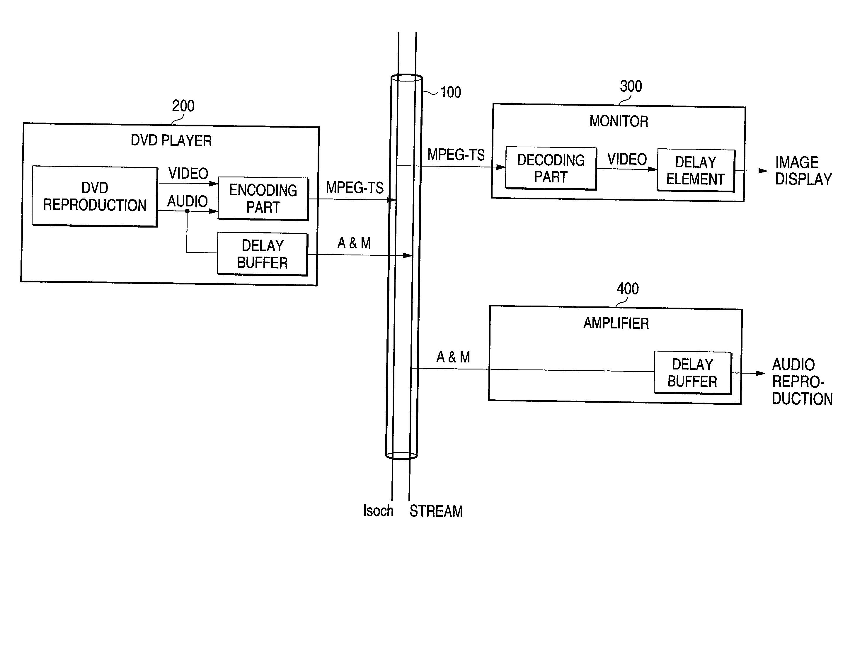
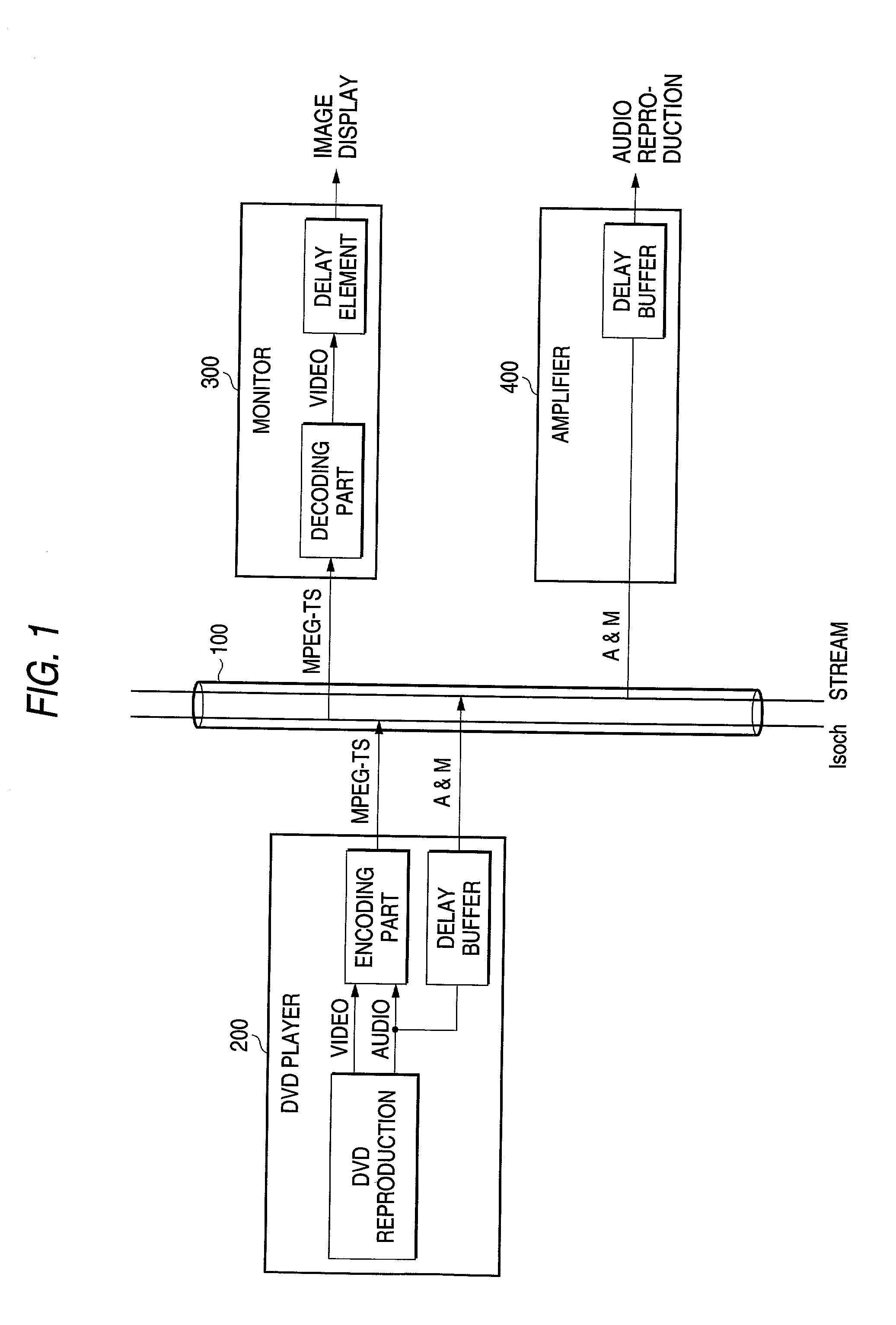
[0034] FIG. 5 shows a first embodiment, and a delay time setting request is sent out from a monitor to an amplifier and based on this request, the amplifier sets delay time in a delay buffer and answers the monitor a message to the effect that the setting is completed. Since a time lag between video and audio is caused by an intrinsic delay element such as pixel conversion made within the monitor, the video and the audio can be synchronized by delaying output of an audio signal by delay time occurring due to this delay element.
[0035] Next, a flow of control commands between a monitor and an amplifier will be described with reference to a transmission form on a serial bus shown in FIG. 6. Each information about audio data of an A&M method sent out from a DVD player, a control command indicating a delay time setting request sent out from the monitor, a control command indicating a delay time setting completion sent out from the amplifier as an answer to the control command indicating ...
second embodiment
[0041] FIG. 8 shows a second embodiment, and a delay time acquisition request is sent out from a DVD player to a monitor and based on this request, the monitor answers the DVD player delay time information caused by an intrinsic delay element. Next, the DVD player sends out a delay time setting request to an amplifier and based on this request, the amplifier sets delay time in a delay buffer and answers the DVD player a message to the effect that the setting is completed. In this manner, the DVD player acquires the delay time information caused by the intrinsic delay element made within the monitor and the amplifier delays output of an audio signal by the delay time sent out from the DVD player and thereby, video and audio can be synchronized.
[0042] Next, a flow of control commands between a DVD player and a monitor and control commands between a DVD player and an amplifier will be described with reference to a transmission form on a serial bus shown in FIG. 9. Each information abou...
third embodiment
[0043] FIG. 10 shows a third embodiment, and a delay time acquisition request is sent out from an amplifier to a monitor and based on this request, the monitor sends out delay time information caused by an intrinsic delay element such as pixel conversion made within the monitor to the amplifier, and the amplifier sets delay time in a delay buffer. In this manner, the amplifier acquires the delay time information caused by the intrinsic delay element made within the monitor and the amplifier delays output of an audio signal by the delay time sent out from the monitor and thereby, video and audio can be synchronized.
[0044] Next, a flow of control commands between an amplifier and a monitor will be described with reference to a transmission form on a serial bus shown in FIG. 11. Each information about audio data of an A&M method sent out from a DVD player, a control command indicating delay time information sent out from the monitor, a control command indicating a delay time acquisitio...
PUM
| Property | Measurement | Unit |
|---|---|---|
| delay time | aaaaa | aaaaa |
| delay time | aaaaa | aaaaa |
| time lag | aaaaa | aaaaa |
Abstract
Description
Claims
Application Information
 - R&D
- Intellectual Property
- Life Sciences
- Materials
- Tech Scout
- Unparalleled Data Quality
- Higher Quality Content
- 60% Fewer Hallucinations
Browse by: Latest US Patents, China's latest patents, Technical Efficacy Thesaurus, Application Domain, Technology Topic, Popular Technical Reports.
© 2025 PatSnap. All rights reserved.Legal|Privacy policy|Modern Slavery Act Transparency Statement|Sitemap|About US| Contact US: help@patsnap.com


