
Initiator assembly and gas generator using the same

a technology of gas generator and igniter, which is applied in the direction of electric fuzes, pedestrian/occupant safety arrangements, vehicular safety arrangements, etc., can solve the problems of high possibility of defective products being produced, increased manufacturing costs, and deterioration of priming (explosives)

Inactive Publication Date: 2002-11-28
DAICEL CHEM IND LTD
View PDF7 Cites 49 Cited by
  • Summary
  • Abstract
  • Description
  • Claims
  • Application Information

AI Technical Summary

Benefits of technology

[0012] The present invention also provides an initiator assembly which can maintain the initial performance even if the initiator assembly is used for a long term in a state in which a priming (explosives) is not moisture-absorbed or deteriorated by permeation of moisture.
[0013] The present invention also provides an initiator assembly capable of reliably holding the conductive pin even if the initiator assembly is exposed to a high temperature.

Problems solved by technology

Further, since the conventional initiator assembly (electric type initiator) is formed by combining a lot of parts, the steps in a manufacturing process are necessarily increased, and thereby a manufacturing cost is increased.
Further, since many steps in a manufacturing processes are required, a possibility such that defective products may be produced also becomes high.
However, in the header made of the nylon 6, a priming (explosives) is moisture-absorbed and deteriorated due to permeation of a moisture, and there may be a possibility such that the initial performance of the initiator can not be obtained due to the use for many years under some environment.
In the conventional initiator assembly, since the conductive pin constituting the electric type initiator is held by the molded member made of a resin material, the initiator assembly is exposed to a high temperature, and when the resin portion is melted, there is a possibility that the conductive pin can not be reliably held.
In such a case, although the priming is charged under pressure, the priming moves toward the space, contact between the priming and the bridge wire is released, and ignition failure may be caused.

Method used


Image

  • Initiator assembly and gas generator using the same
  • Initiator assembly and gas generator using the same
  • Initiator assembly and gas generator using the same

Examples


embodiment 2

[0113] Embodiment 2

[0114] FIGS. 6 and 7 show an embodiment of a gas generator for an air bag formed by using the initiator assembly described above.

[0115] In the gas generator, a housing is formed by combining a diffuser shell 101 in which a gas discharge port 104 is formed and a closure shell 102 closing the diffuser shell, and the housing 103 includes an igniting means comprising the initiator assembly 100 and a gas generating means 105 to be ignited and burnt upon activation of the igniting means for generating a working gas to inflate an air bag (a bag body), and a filter means 106 for purifying and / or cooling the working gas generated by combustion of the gas generating means 105.

[0116] In the gas generator shown in FIG. 6, an inner cylindrical member 108 provided with a plurality of flame-transferring ports 107 on a circumferential wall is arranged in the center inside the housing, a space 109 for storing the igniting means is formed inside the inner cylindrical member 108, an...


PUM


Abstract

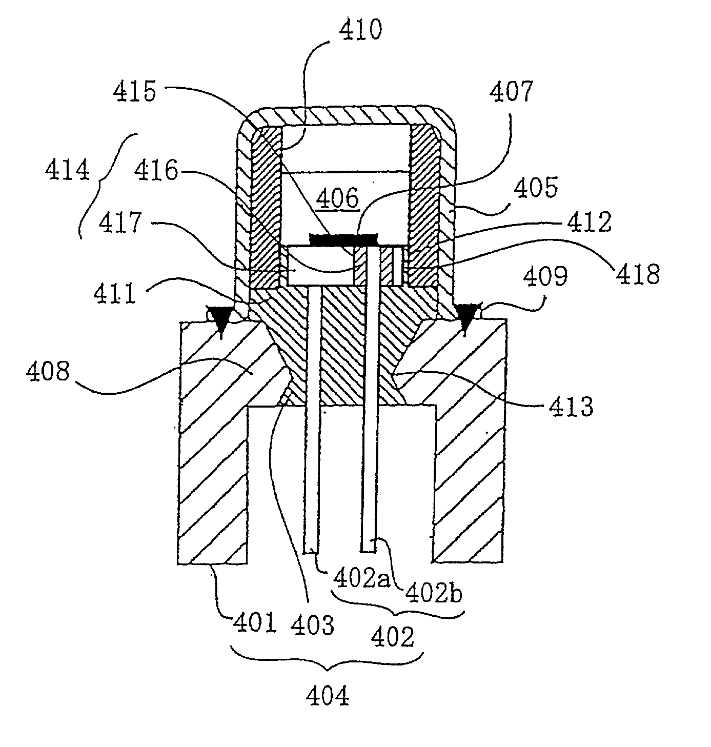
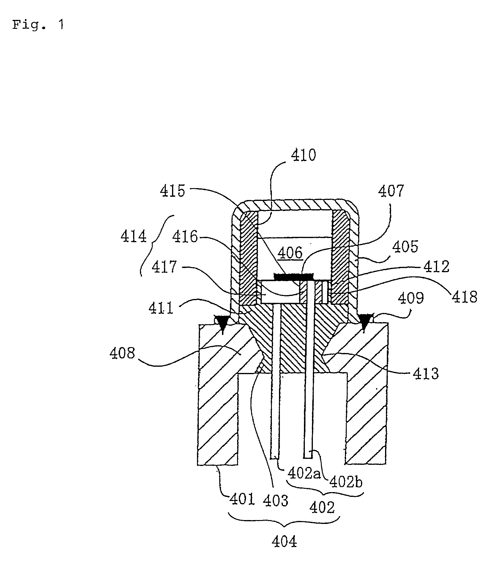
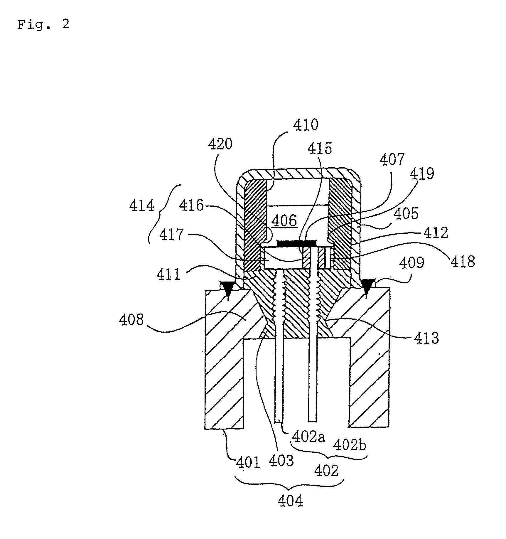
The present invention provides an initiator assembly in which the number of constituent parts is reduced, manufacturing facilitation of the constituent parts themselves is enhanced, the initial performance can be maintained even if the initiator assembly is used for a long term, and the conductive pins can reliably be held even if the initiator assembly is exposed to a high temperature. The initiator assembly comprises an electric type initiator and a metal collar for holding the electric type initiator, head portions of the conductive pins of the electric type initiator are electrically insulated from each other but are integral with each other, and the head portions are a disk in shape as a whole.

Description

[0001] The present invention relates to an initiator assembly comprising an electric type initiator which is activated by an electric signal at a time of collision, and more particularly to an initiator assembly which is used in a gas generator for an air bag or a gas generator for a seat belt pretensioner which are safety system of a motor vehicle for burning and / or expanding a propellant (e.g., a gas generating means), and the invention also relates to a gas generator using the initiator assembly.PRIOR ART[0002] The air bag apparatus and the seat belt pretensioner play an important part on the decrease in deaths and injuries caused by collisions. The initiator assembly comprises an electrical type initiator activated by the electric signal outputted from a collision detecting system, the initiator assembly is fixed to these safety devices via a metal collar and has a function of starting the operation of these safety devices.[0003] As an electrical initiator in conventional initia...

Claims


Application Information

Patent Timeline
IPC IPC(8): B60R21/26B60R21/264F42B3/12
CPCB60R21/2644F42B3/195F42B3/103B60R2021/26029
Inventor KUBOZUKA, SATOSHIODA, SHINGO
Owner DAICEL CHEM IND LTD
Learn More