Heat exchanger and manufacturing method of home appliance including the heat exchanger

Pending Publication Date: 2021-02-18
LG ELECTRONICS INC
View PDF0 Cites 0 Cited by
  • Summary
  • Abstract
  • Description
  • Claims
  • Application Information

AI Technical Summary

Benefits of technology

The present patent proposes a way to prevent rust or corrosion on a heat exchanger by coating it, particularly on copper pipes. It also provides information on the dimensions of a weld zone that can help suppress corrosion, and the thickness of a coating layer that effectively prevents rust or corrosion.

Problems solved by technology

As a usage time of the heat exchanger accumulates, rust or corrosion may occur on surfaces of the pipe or fins.
Meanwhile, research related to improvement of corrosion resistance through coating is insufficient in relation to copper.
The technology disclosed in the patent document is far from the purpose of preventing oxidation of copper in that it rather actively oxidizes copper.
Meanwhile, an occurrence of rust or corrosion in the heat exchanger is strongly influenced by surroundings in which the heat exchanger is used.
For example, when a heat exchanger is used in a clothes treatment apparatus such as a dryer, as refrigerant evaporates from a heat exchanger used as an evaporator, water in the air, which is an object of heat exchange of the refrigerant, condenses, and condensate generated therefrom causes rust or corrosion.
In particular, copper pipes are welded in a manufacturing process of the heat exchanger, and a tendency of rust or corrosion of the heat exchanger to occur in weld zones is very strong.
Furthermore, when a heat exchanger to which a coating capable of preventing rust or corrosion is applied is installed in a home appliance, deterioration of the coating may occur in a subsequent process.
In particular, when a distance between a rim of the burr and an outer surface of the straight tube is less than 0.4 mm, welding may be impossible or leaking may occur due to a welding material.
In addition, when the distance between the rim of the burr and the outer surface of the straight tube exceeds 1.8 mm, rust or corrosion is easily generated due to the structure.

Method used


Image

  • Heat exchanger and manufacturing method of home appliance including the heat exchanger
  • Heat exchanger and manufacturing method of home appliance including the heat exchanger
  • Heat exchanger and manufacturing method of home appliance including the heat exchanger

Examples


Embodiment Construction

[0059]Hereinafter, a heat exchanger and a manufacturing method of a home appliance including the heat exchanger according to the present disclosure will be described in detail with reference to the drawings.

[0060]For the sake of brief description with reference to the drawings, the same or equivalent components will be provided with the same reference numbers, and description thereof will not be repeated.

[0061]It will be understood that when an element is referred to as being “connected with” another element, the element can be connected with the another element or intervening elements may also be present. In contrast, when an element is referred to as being “directly connected with” another element, there are no intervening elements present.

[0062]A singular representation may include a plural representation unless it represents a definitely different meaning from the context.

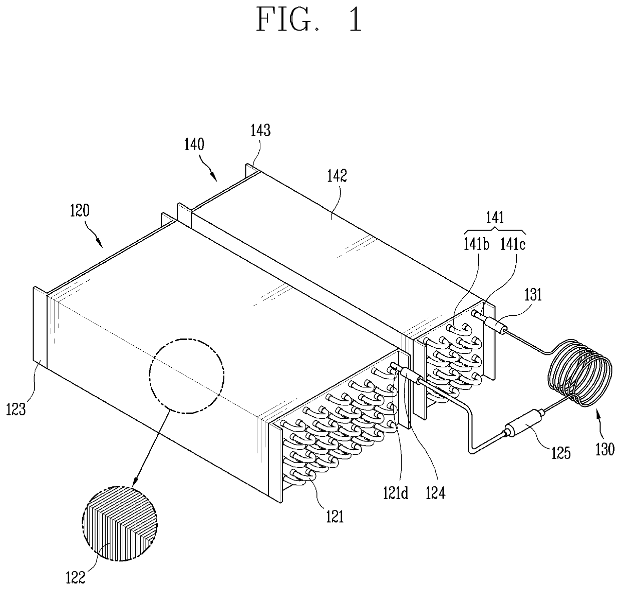
[0063]FIG. 1 is a perspective view of a heat exchanger 120, 140 related to an embodiment of the present disc...


PUM

PropertyMeasurementUnit
Lengthaaaaaaaaaa
Lengthaaaaaaaaaa
Lengthaaaaaaaaaa

Abstract

A heat exchanger includes: a copper pipe forming a refrigerant circulation passage; and a plurality of fins arranged at positions spaced apart from each other along one direction and coupled to an outer circumferential surface of the copper pipe, wherein the copper pipe includes: a plurality of straight tubes extending along the arranged direction of the plurality of fins; and a plurality of return bends connected to one end of one of the plurality of straight tubes and one end of another one of the plurality of straight tubes by welding, wherein burrs having a circumference greater than an outer diameter of each straight tube are formed at both ends of the plurality of straight tubes, a distance between a rim of the burr and an outer surface of the straight tube is 0.4 mm to 1.8 mm.

Description

CROSS-REFERENCE TO RELATED APPLICATIONS[0001]Pursuant to 35 U.S.C. § 119(a), this application claims the benefit of the earlier filing date and the right of priority to Korean Patent Application No. 10-2019-0099748, filed on Aug. 14, 2019, and Korean Patent Application No. 10-2020-0010694, filed on Jan. 29, 2020, the contents of which are incorporated by reference herein in their entirety.BACKGROUND1. Technical Field[0002]The present disclosure relates to a heat exchanger and a home appliance including the heat exchanger.2. Description of the Related Art[0003]There are many types of heat exchangers, among them, a heat exchanger commonly used in a home appliance has a form in which a plurality of fins is coupled to an outer circumferential surface of a pipe. Inside the pipe, refrigerant flows, and the fins facilitate heat exchange between air and heat through the pipe.[0004]As a usage time of the heat exchanger accumulates, rust or corrosion may occur on surfaces of the pipe or fins....

Claims


Application Information

Patent Timeline
IPC IPC(8): D06F58/20F28F19/02D06F58/02D06F58/24
CPCD06F58/206D06F58/24D06F58/02F28F19/02C09D5/08C09D175/04F28D1/0477F28D1/0417F28F1/32F28F21/085F28F19/04F28F2245/00F28F2275/045
Inventor HAN, SANGKWONKIM, MYEONGDEOKCHOI, JEONGGEUN
Owner LG ELECTRONICS INC
Why Eureka
Try Eureka