
Stop changing device for a camera

a technology for changing devices and cameras, applied in the direction of cameras, exposure control, instruments, etc., can solve the problems of product quality deterioration, increased printing costs, and poor photographic image quality

Inactive Publication Date: 2002-12-05
FUJIFILM HLDG CORP +1
View PDF1 Cites 4 Cited by
  • Summary
  • Abstract
  • Description
  • Claims
  • Application Information

AI Technical Summary

Benefits of technology

[0010] It is a second object of the present invention to provide a stop changing device for a camera in which an exposure amount is adjusted to prevent an underexposure from occurring in a dark place.
[0014] According to the present invention, a structure of the stop changing device may be simplified and the manufacture cost thereof may be reduced. Further, it is possible to adjust an exposure amount without enlarging a size of the stop changing device so that a picture may be taken at a dark place without causing underexposing.

Problems solved by technology

If subject brightness is outside the above-noted range, the photographic image quality deteriorates.
Hence, product quality deteriorates.
Moreover, printing time is prolonged in a laboratory so that printing cost increases.
Further, since the depth of field becomes shallow, the background of the main subject is out of focus.
Meanwhile, when a picture is taken at an obscurity place, for example at the evening outdoors, many of photographers judge that the flash light is unnecessary.
Accordingly, the smaller stop aperture is used for photographing so that it is likely to cause an underexposure.

Method used


Image

  • Stop changing device for a camera
  • Stop changing device for a camera
  • Stop changing device for a camera

Examples


Embodiment Construction

)

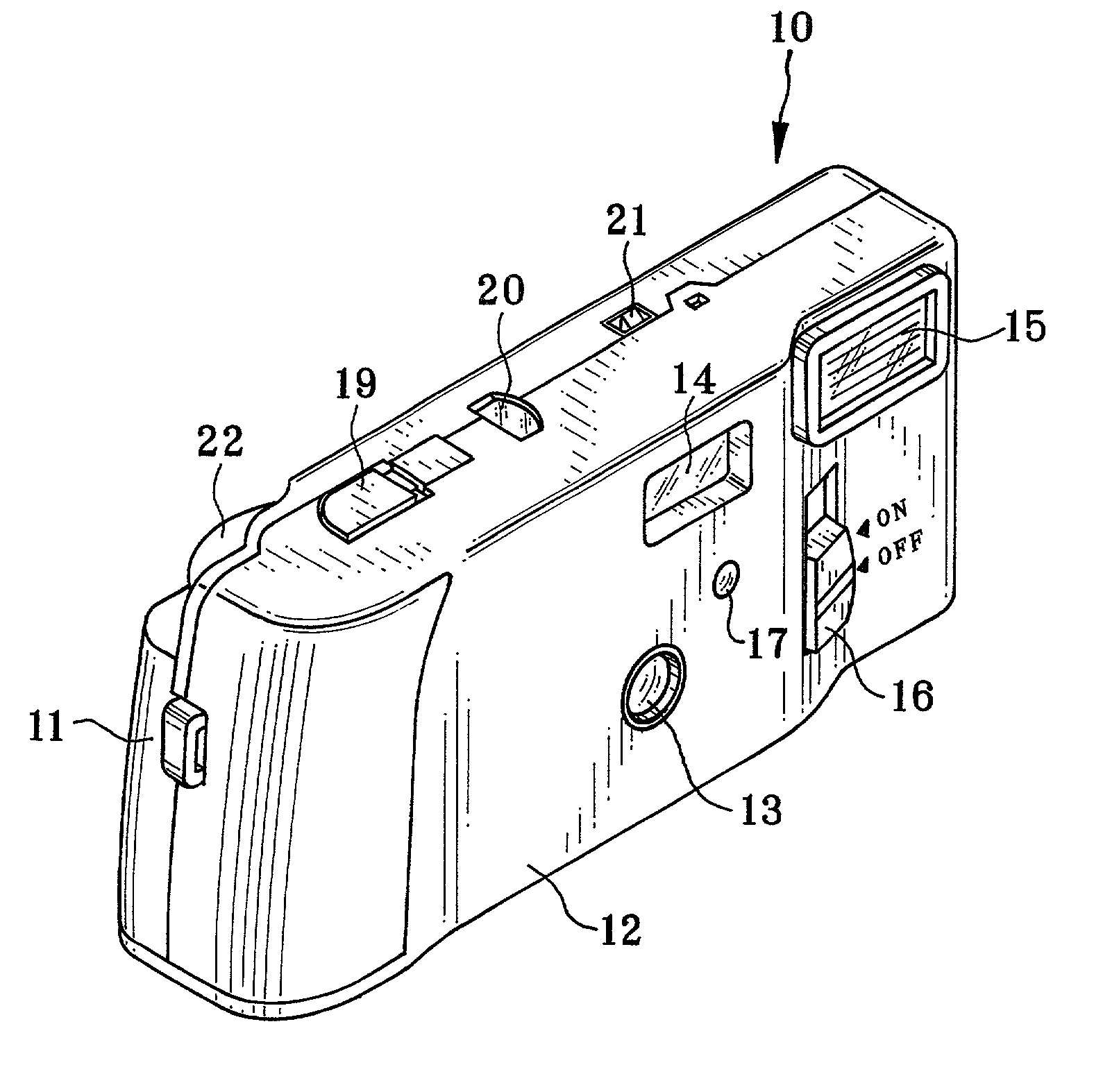
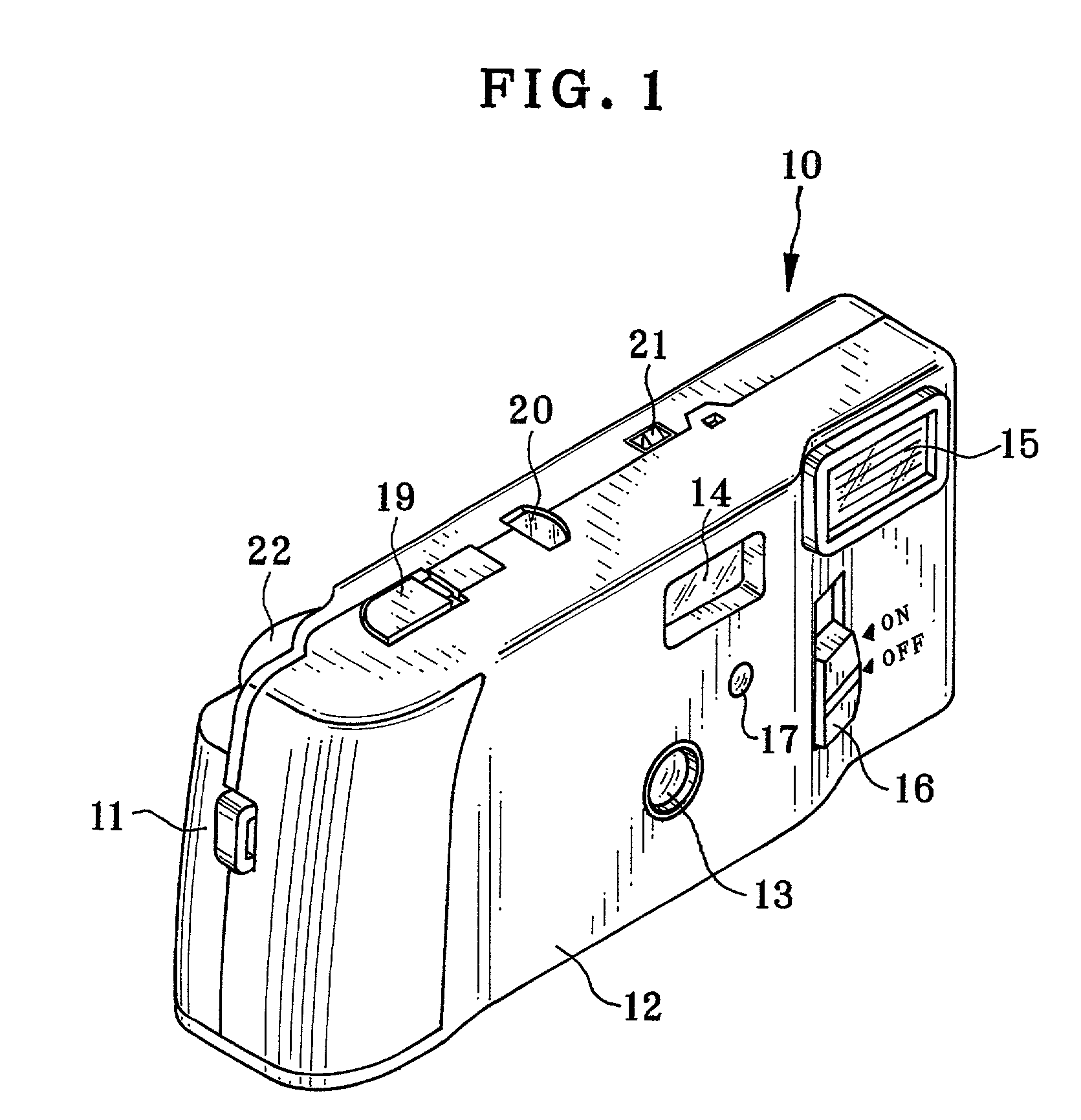
[0030] As shown in FIG. 1, a lens-fitted photo film unit (hereinafter, film unit) 10 is constituted of a unit body 11 and an outer label 12 for covering a surface of the unit body 11. The front of the unit body 11 is provided with a taking lens 13, a viewfinder lens 14, a flash portion 15, a flash switch 16, and a light receiving element 17 for measuring subject brightness. The top of the unit body 11 is provided with a release button 19, a film counter 20, and a confirmation window for confirming flash charging. Incidentally, a part of a take-up wheel 22 emerges through the back of the unit body 11.

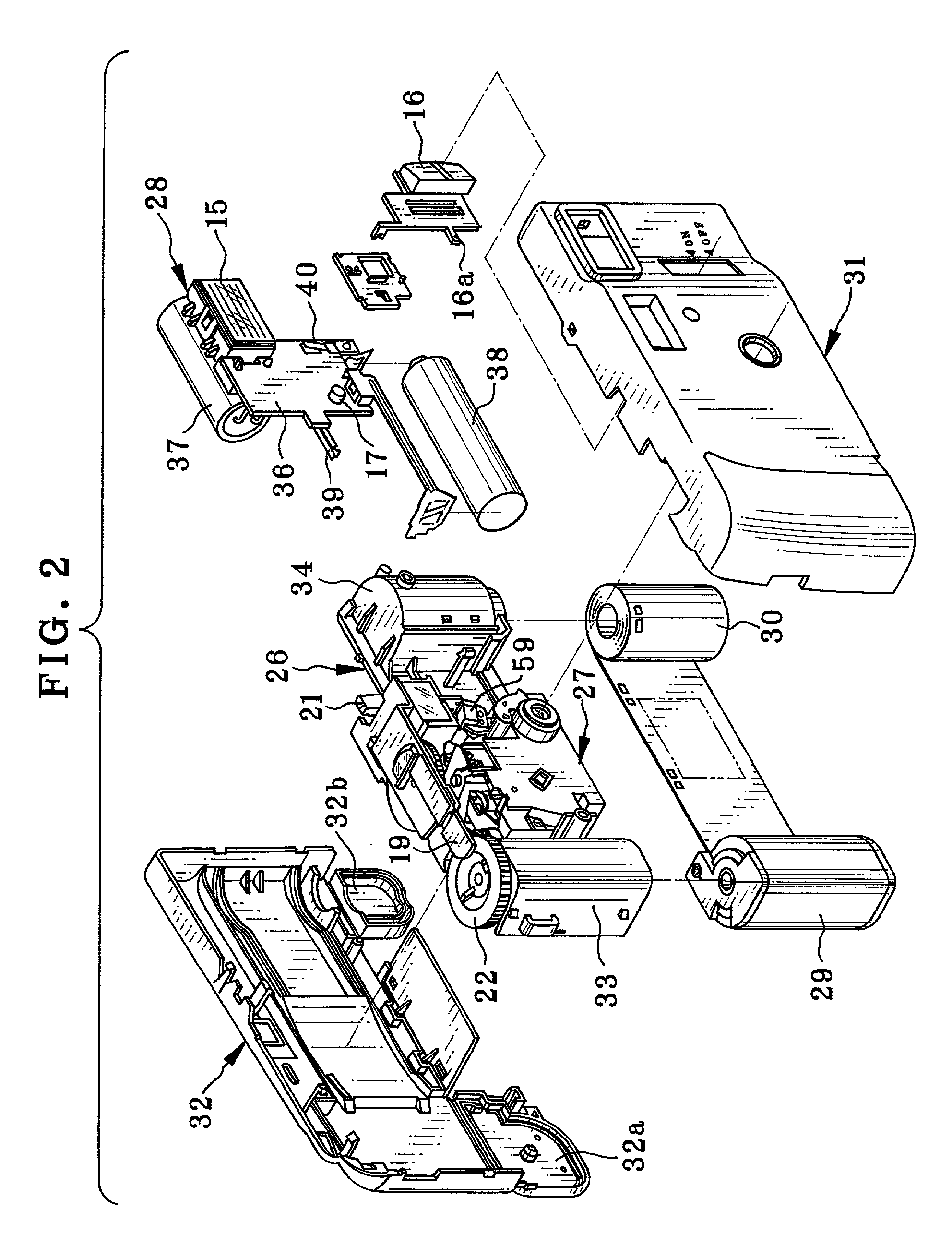
[0031] As shown in FIG. 2, the unit body 11 is constituted of a main body 26, an exposure unit 27, a flash unit 28, a cartridge shell 29, a photographic film 30, a front cover 31, and a rear cover 32. The main body 26 is constituted of an exposure frame (not shown) for defining an exposure area of the photographic film 30, a cartridge chamber 33 for containing the cartridge shell 29, an...


PUM

PropertyMeasurementUnit
Diameteraaaaaaaaaa
Shapeaaaaaaaaaa
Brightnessaaaaaaaaaa

Abstract

A lens-fitted photo film unit is provided with a movable stop plate formed with small and middle stop apertures. The small stop aperture has a smaller diameter, and the middle stop aperture is larger than the small stop aperture. A fixed large stop aperture, which is larger than the middle stop aperture, is disposed behind the movable stop plate. The movable stop plate is moved to position the small stop aperture at a photographic optical axis when subject brightness is a predetermined reference value or more. Similarly, the middle stop aperture is positioned at the optical axis when the subject brightness is less than the reference value and a flash switch is turned off. Further, the fixed large stop aperture is set to the optical axis when the subject brightness is less than the reference value and the flash switch is turned on.

Description

[0001] 1. Field of the Invention[0002] The present invention relates to a stop changing device for a camera, and particularly to a stop changing device favorable to a single-use camera of a lens-fitted photo film unit and so forth.[0003] 2. Description of the Related Art[0004] As a sort of simplified cameras, lens-fitted photo film units of various types are put in the market by the present assignee. The lens-fitted photo film unit includes a simple photographing mechanism including a taking lens, a shutter mechanism, and so forth. Further, the lens-fitted photo film unit is loaded with an unexposed photographic film in advance. A user can easily take a picture having good image quality. As to the lens-fitted photo film unit, f-number and shutter speed of the taking lens are fixed for the purpose of lowering its price and reducing its size so that exposure conditions are constant. Thus, a range of a photographic condition for properly photographing a main subject and the background ...

Claims


Application Information

Patent Timeline
IPC IPC(8): C23C16/455G03B7/095C23C16/54G03B9/02G03B9/04G03B9/07G03B15/05G03C3/00
CPCC23C16/455G03B9/02C23C16/545C23C16/45561
Inventor KAMATA, KAZUO
Owner FUJIFILM HLDG CORP
Learn More