
Dependent object processing for triggers

a technology of object processing and triggers, applied in the field of information processing, can solve problems such as further complicated situation, user may make changes to tables, and objects may be missing or differen

Inactive Publication Date: 2002-12-05
IBM CORP
View PDF3 Cites 15 Cited by
  • Summary
  • Abstract
  • Description
  • Claims
  • Application Information

AI Technical Summary

Problems solved by technology

One problem / limitation with current trigger implementations is that a user may make changes to a table unaware of a potential impact on the trigger.
Specifically, the impact results because, following the change, objects may be missing or different.
This situation is further complicated when T1 is later restored or another table T1 is created on the system because the table the user intended for the trigger to use is unknown.
As a result of the user's actions, the wrong table or library may be used, whereby the trigger produces incorrect results.
A conventional RDBMS is not equipped to handle the foregoing situations.
This approach is both time-consuming and replete with the potential for human error.

Method used


Image

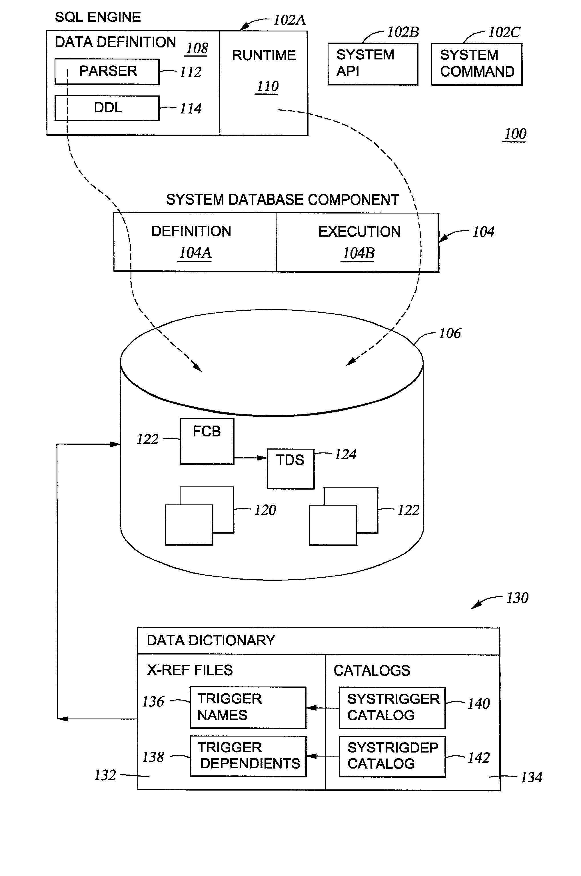
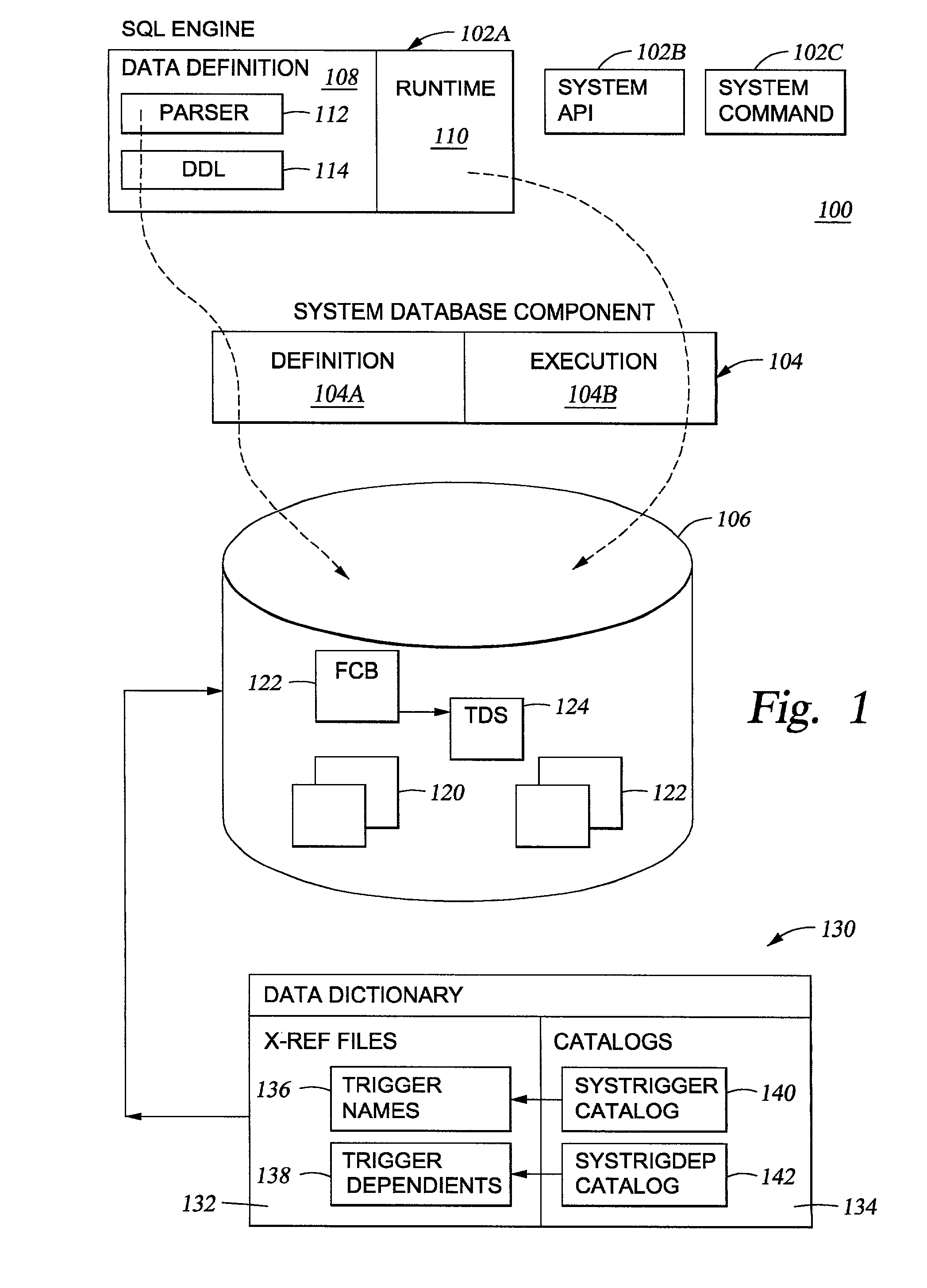
  • Dependent object processing for triggers
  • Dependent object processing for triggers
  • Dependent object processing for triggers

Examples


Embodiment Construction

001 CREATE TRIGGER LIB1.TRIG 2 002 AFTER UPDATE OF COL1, COL2, COL3 on LIB1.TABLE1 003 REFRENCING OLD AS X1 NEW AS X2 004 FOR EACH ROW MODE DB2SQL 005 WHEN (X1.COL1 = 1) 006 BEGIN ATOMIC 007 INSERT INTO TABLE1 (COL1, COL2, COL3) VALUES(1,2,3); 008 INSERT INTO TABLE3 (COL1, COL2, COL3,) VALUES(7,8,9); 009 END

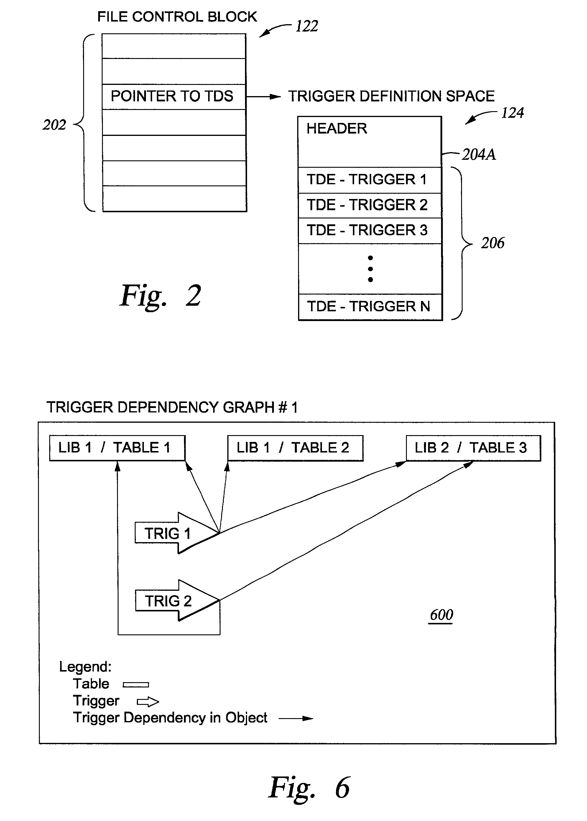
[0065] However, in this case the CREATE TRIGGER Statement III does not include the syntax INSERT INTO TABLE2. The object dependency for each trigger is illustrated by the relationship chart 600 shown in FIG. 6.

[0066] In some embodiments, methods are provided that allow a user to identify potential problems using objects that had been modified in some way by certain operations. Illustrative modifying operations include the SQL RENAME statement and the system functions to rename a file, renaming library, move a file and restore to a different library.

[0067] In one embodiment, if a table is renamed and the table has self referencing triggers defined on it, then the trigger will be s...


PUM


Abstract

Methods, systems and articles of manufacture are provided for setting a state of triggers between operative and inoperative. In an operative state the trigger may be called during triggering I / O operations such as Insert, Update and Delete. The inoperative state indicates that the system has detected a condition requiring user intervention. In a particular embodiment, a database management system (DBMS) will analyze the function being performed on a table (such as a rename of the table) and with dependent object data, the DBMS will determine if the trigger is self-referencing. If so, the trigger made inoperative. Making the trigger inoperative and requiring user intervention prevents the system from potentially producing undesired results. In another embodiment, a determination of dependency is made upon receiving a database command to affect an object. According to the type of command, the object and its dependents are either affected or unaffected.

Description

[0001] 1. Field of the Invention[0002] Embodiments of the present invention relate to information processing and more specifically to management of database triggers where dependencies exist.[0003] 2. Background of the Related Art[0004] Databases are computerized information storage and retrieval systems. A relational database management system (RDBMS) is a computer database management system that uses relational techniques for storing and retrieving data. Relational databases are computerized information storage and retrieval systems in which data in the form of tables (formally denominated "relations") are typically stored for use on disk drives or similar mass data stores. A "table" includes a set of rows (formally denominated "tuples" or "records") spanning several columns. Reference is made to C. J. Date, An Introduction to Database Systems, 6th edition, Addison-Wesley Publishing Co. Reading, Mass. (1994) for an comprehensive general treatment of the relational database art.[00...

Claims


Application Information

Patent Timeline
IPC IPC(8): G06F7/00G06F17/30
CPCY10S707/955Y10S707/99943Y10S707/99932G06F17/3051Y10S707/99934Y10S707/99942Y10S707/99933G06F16/24565
Inventor ANDERSON, MARK JOHNBRETTIN, KEVIN ROBERTBRUHNKE, RUSSELL EDWARDGILBERTSON, KYLE ERICNYLAND, RITCHIE LEEPARROTT, RICHARD DONALDPASSE, KATHY LYNNROLFE, RANDY KEITHROMANO, SUSAN LIISASAXMAN, RENEE KRISTINSTEINBRINK, KATHRYN ROSETHEUER, MARK WILLIAMTRIEBENBACH, JONATHAN LEEVENZ, MICHAEL ALANVOLD, JANE ANN
Owner IBM CORP
Learn More