Shouldered ramp for streetwork cover and method of use

Inactive Publication Date: 2002-12-12
SSR MARINE FENDERS
View PDF0 Cites 19 Cited by
  • Summary
  • Abstract
  • Description
  • Claims
  • Application Information

AI Technical Summary

Benefits of technology

0028] In any case, when the desired number or amount of ramp strips are laid, and optionally anchored to the pavement via pavement attachment devices engaged for such purposes through the optional apertures provided as attachment points, the cover is laid onto the shoulder(s) of the ramp strip(s) and seated thereon or therein. This seating acts to weight and hold down the ramp strip(s) generally, and also to cushion the cover plate somewhat and act also as an optional sound dampening or deadening medium to reduce or eliminate the accompanying clanking sounds of using such covers. With the ramp strips held in place by the weight of the plate, and optionally by supplemental anchors, vehicles are enabled to approach the cover plate, ride up the short ramp and onto the plate, and off the plate on the other side without substantially dislodging any ramp from its proximity to the edge of the cover plate either on the wheel approach to the plate top or the wheel take off on the other side, thereby imparting little or no appreciable impact to the plate.
0029] A method of effecting a removable and reusable work site excavation cover includes some or all of the following steps: determining a suitable cover size and an optimal position and arrangement of cover plate(s) to effect the desired cover size; laying one or more rubber strips each having a relatively flat shoulder portion and a triangular or wedge cross-sectioned ramp portion (preferably integrally cast or otherwise permanently joined to one another) about the periphery of the cover size so as to form a bed or seat comprised of the combined sho

Problems solved by technology

Laying such thick and potentially sharp-edged plates over excavation work generally accomplishes the cruder goals outlined above, but introduces a new problem, which as yet has not been satisfactorily addressed.
As vehicles approach, and then ride over, the plate, the vehicle wheels are compelled to jump, anywhere from a hardly noticeable distance in a shock insulated suspension system, to a severe and unpleasant jolt in a hard suspension system.
In addition, undesirable and potentially dangerous impact momentum is imparted to the plate by each wheel impact, the cumulative effect of which may be to move the heavy plate and cause exposure of the work site and/or danger

Method used


Image

  • Shouldered ramp for streetwork cover and method of use
  • Shouldered ramp for streetwork cover and method of use
  • Shouldered ramp for streetwork cover and method of use

Examples


Embodiment Construction

[0039] Turning now to the drawings, the invention will be described in a preferred embodiment by reference to the numerals of the drawing figures wherein like numbers indicate like parts.

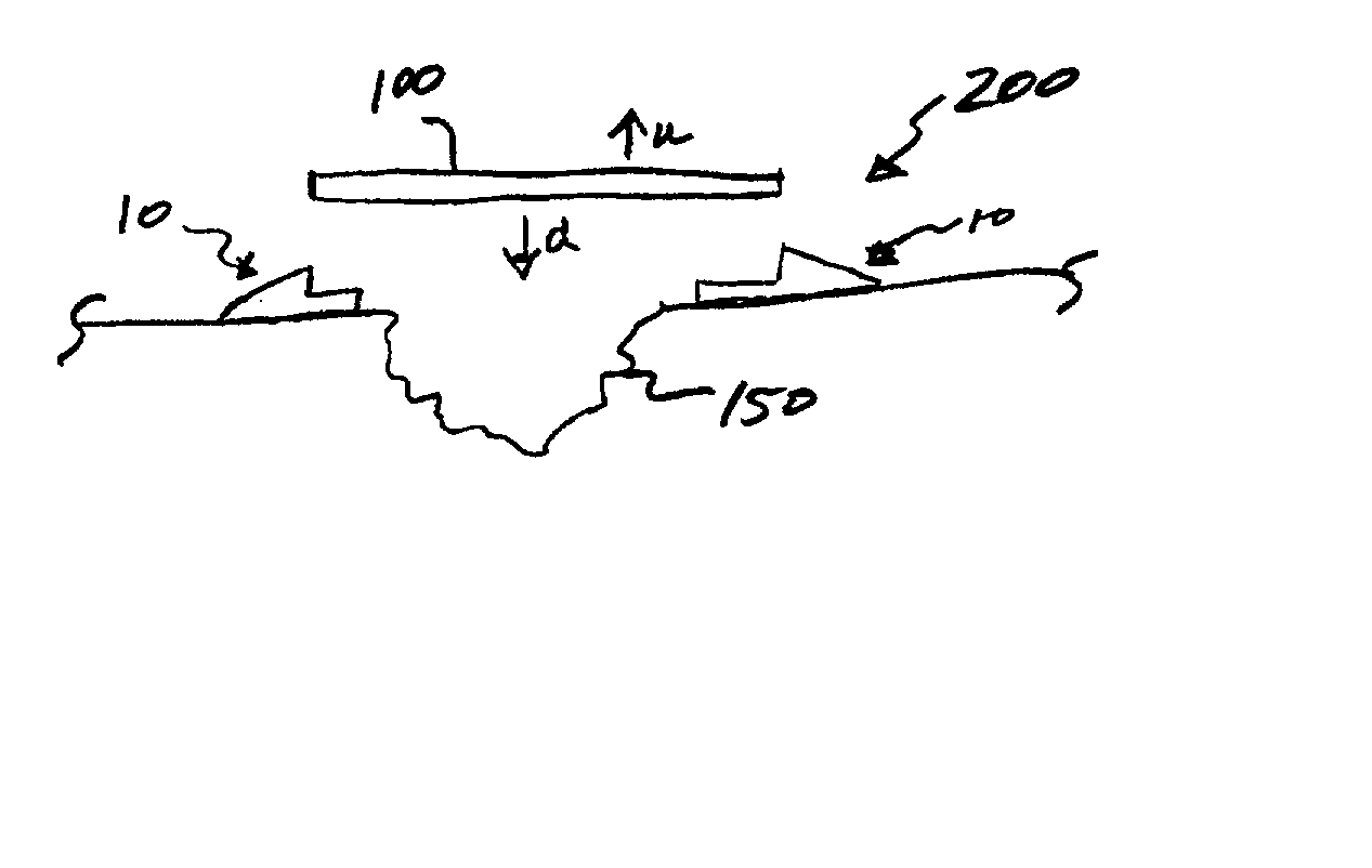
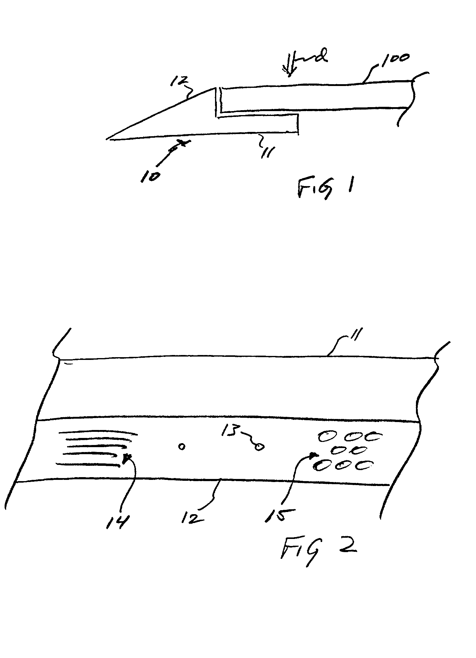
[0040] FIG. 1 is a side elevation of ramp strip 10 with plate 100 lowered in direction of arrow d down onto shoulder (or bed) 11 of strip 10.

[0041] FIG. 2 is a partial plan view of ramp strip 10 (without plate 100), illustrating preferred layout of shoulder 11 and ramp 12. Optional anchor apertures 13 and optional traction features such as grooves 14 and holes or dimples 15 are shown.

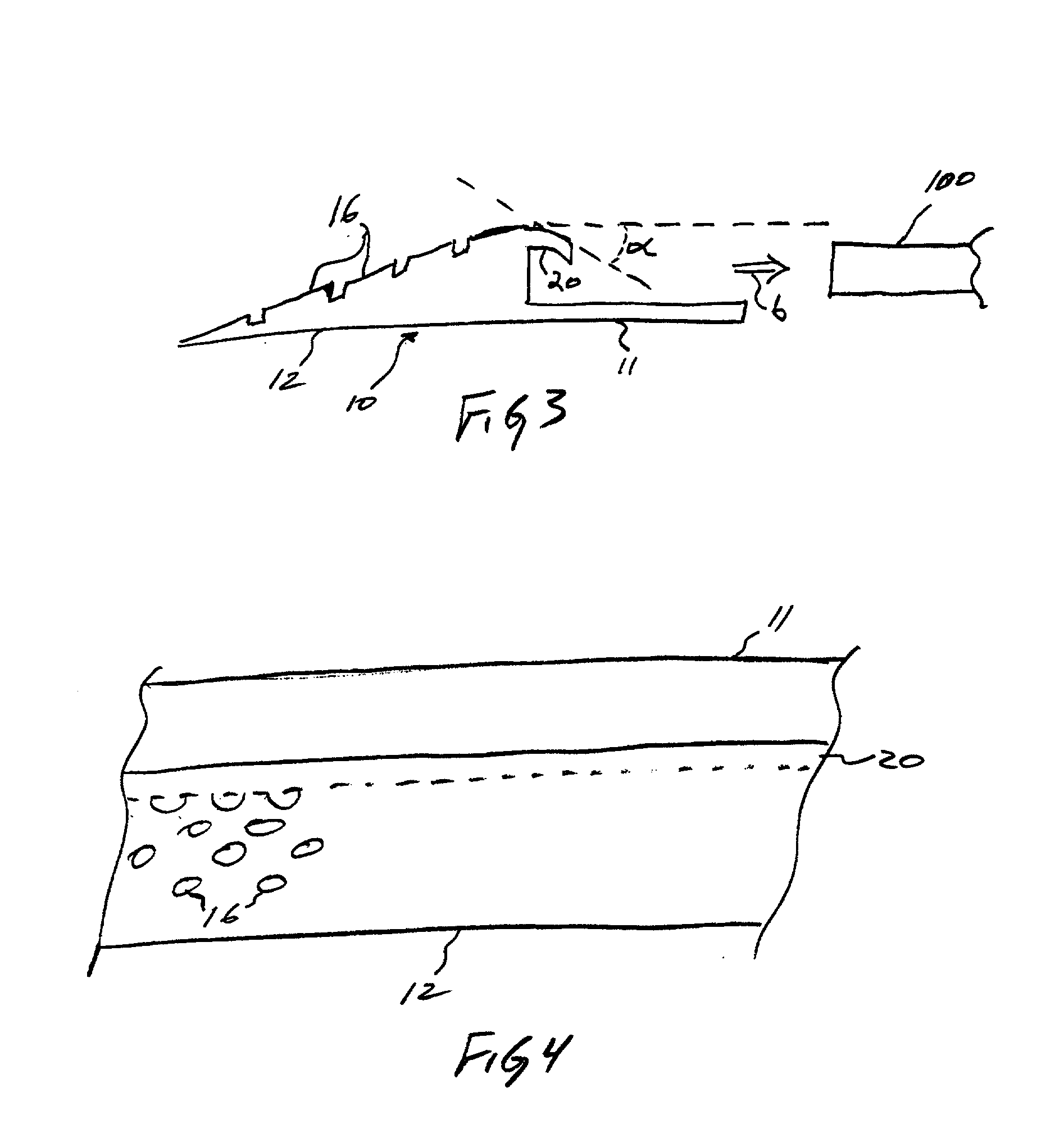
[0042] FIGS. 3 and 4 illustrate an preferred embodiment of ramp strip 10 where ramp 12 has preferred traction features in the form of raised buttons 16 and a depending spring lip 20 depending toward shoulder 11 at angle .alpha.. Ramp strip 10 is moved into engagement with plate 100 in the direction of arrow b. In effecting the engagement, lip 20 is generally displaced and forced upwardly from its resting or unsprung pos...


PUM


Abstract

A road plate ramp strip has a ramp portion and a shoulder portion, preferably integral to one another, such as by integral casting or molding. The ramp strip preferably has a plurality of traction enhancing variations in an upper surface of the ramp, such as buttons grooves, dimples, holes or the like. As an environmental enhancement and to reduce costs, the ramp strip preferably has a constituent composition of a substantial admixture of post-consumer vehicular tire rubber. The ramp strip preferably has a spring lip extending from an upper portion of the ramp portion out over the shoulder portion and downward toward it at an angle .alpha.. The lip is preferably integral to the ramp portion and depends from an upper portion of the ramp out over the shoulder. There is also a method of covering an excavated work place or other surface irregularity with one or more cover plates and ramp strips.

Description

[0001] This application claims priority to U.S. Provisional Application No. 60 / 277,797 filed Mar. 21, 2001.TECHNICAL FIELD[0002] The invention relates to methods and devices for temporary coverage of road and streetwork excavations; more particularly it relates to a shouldered ramp for streetwork cover and method of excavation coverage.BACKGROUND OF THE INVENTION[0003] Road and street excavations are a common sight; such work is usually the result of needed access to buried utilities or actual repair or new construction of road and street surfaces. So that drivers are minimally impacted by the work, and also for safety and so that material in the excavation is not unreasonably exposed to the elements or to risks of theft or mischief, such excavations are usually required to be covered when work is not actually taking place, and the covers, at least in most parts of the United States are typically plate steel, anywhere from {fraction (3 / 4)} inch to 11 / 2 inches in thickness.[0004] Lay...

Claims


Application Information

Patent Timeline
IPC IPC(8): E01C9/08E01C23/06E02D17/10
CPCE01C9/08E02D17/10E01C23/06
Inventor ARMFIELD, GREGORY J.KERBER, DENNIS P.FOLEY, PATRICK THOMAS
Owner SSR MARINE FENDERS
Why Eureka
Try Eureka