Self calibration of transponder apparatus

a transponder and self-calibration technology, applied in the field of self-calibration, can solve the problems of limited procedure, direct measurement of such time intervals, and yield of measurements performed by different techniques

Inactive Publication Date: 2002-12-12
ITT DEFENSE & ELECTRONICS
View PDF0 Cites 13 Cited by
  • Summary
  • Abstract
  • Description
  • Claims
  • Application Information

AI Technical Summary

Benefits of technology

0021] It is still another object of this invention to provide a transponder self calibration method and system for remotely determining the inherent delay in a transponder that is capable of easily informing the radar system regarding the amount of inherent delay in the transponder when the delay is smaller than the pulse width of the transmitted radar pulse.
0022] It is yet another object of this invention to provide a transponder self calibration method and system for remotely determining the inherent delay in a transponder that constantly transponds signals to active radar detectors. Accordingly, a calibration mode which disrupts normal operation is not required.

Problems solved by technology

The necessary accuracy for the measurement of this delay can be in the sub-microsecond range, and direct measurement of such time intervals is a substantial technical challenge.
This procedure is typically limited to the lower range scales.
Since the range is directly related to the time delay, the problem becomes that of determining precisely the elapsed time between reception at the transponder of the pulse transmitted by the ship's radar, and the transmission of the return pulse by the transponder unit.
Measurements performed by these different techniques have yielded results, which disagree.
While modem oscilloscopes have overcome some of the above mentioned measurement difficulties, there remain problems associated with the described prior art delay measurement techniques.
A first problem is that it is a static (one time) calibration as opposed to a continuous calibration.
A second problem is that because the counter circuits in the delay clock may not function perfectly at all ranges and the calibration is performed at a fixed range, a detected delay value may have a further unknown and undeterminable error.
A third problem is that if the transponder delay is smaller than the pulse width of the test pulse, it is not possible to determine the amount of the delay.
A fourth problem is that normal operation of the transponder and receiver must be halted during the calibration process.
Manual calibration of transponders as described above has an inherent limitation that restricts any practical application.
Specifically, any subsequent change in temperature, pressure, stress, strain and the like, will result in an unknown and undeterminable inherent delay in the transponder.
As such, unless a transponder is constantly manually calibrated, the true, real-time, delay of the system cannot be determined.
However, it is impractical to expend manpower to constantly manually calibrate the transponder.
Furthermore, even when a transponder operator calibrates the system in flight, the manual operation is difficult and the results are difficult to communicate to a receiving station in a timely manner.
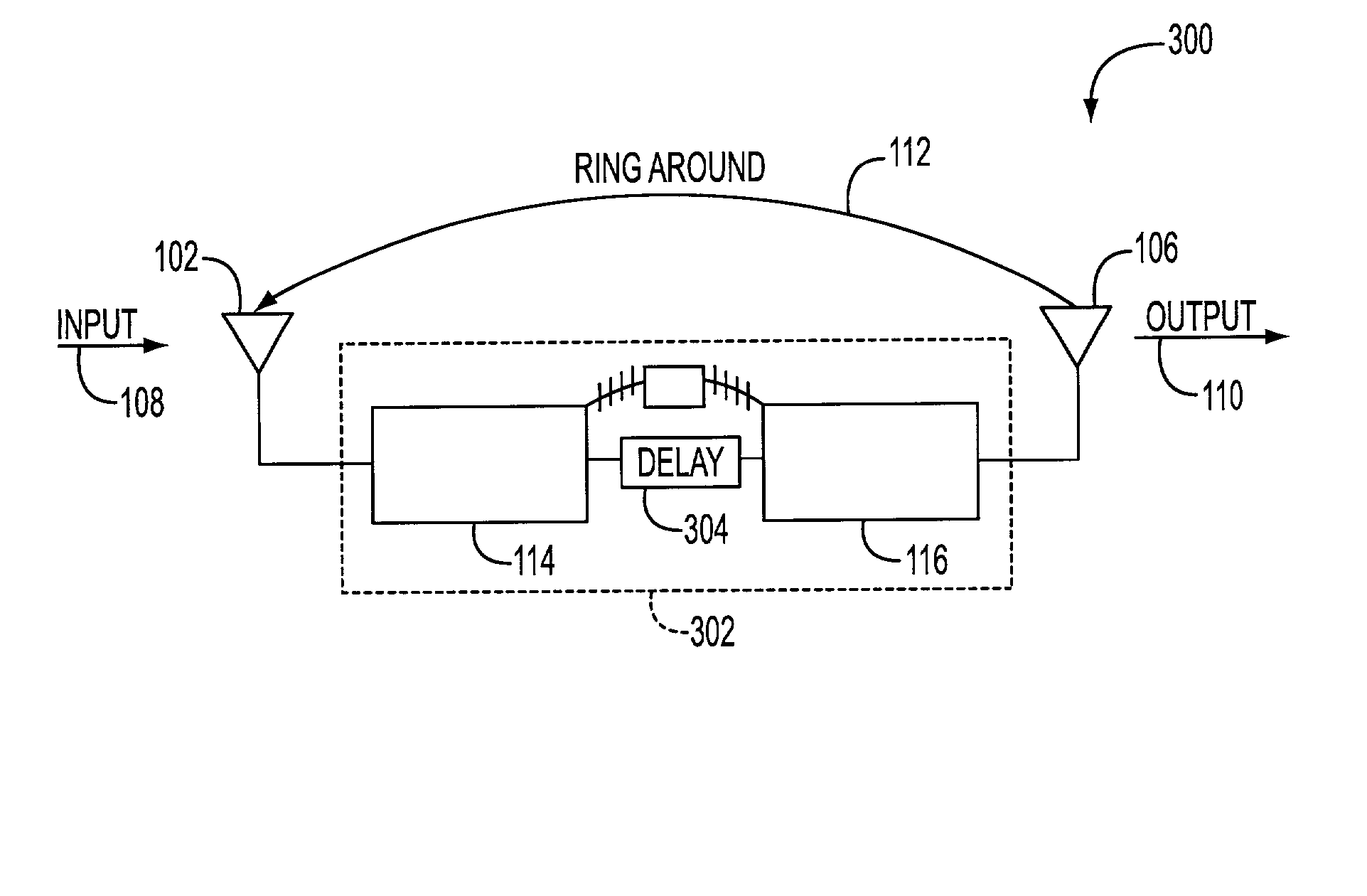
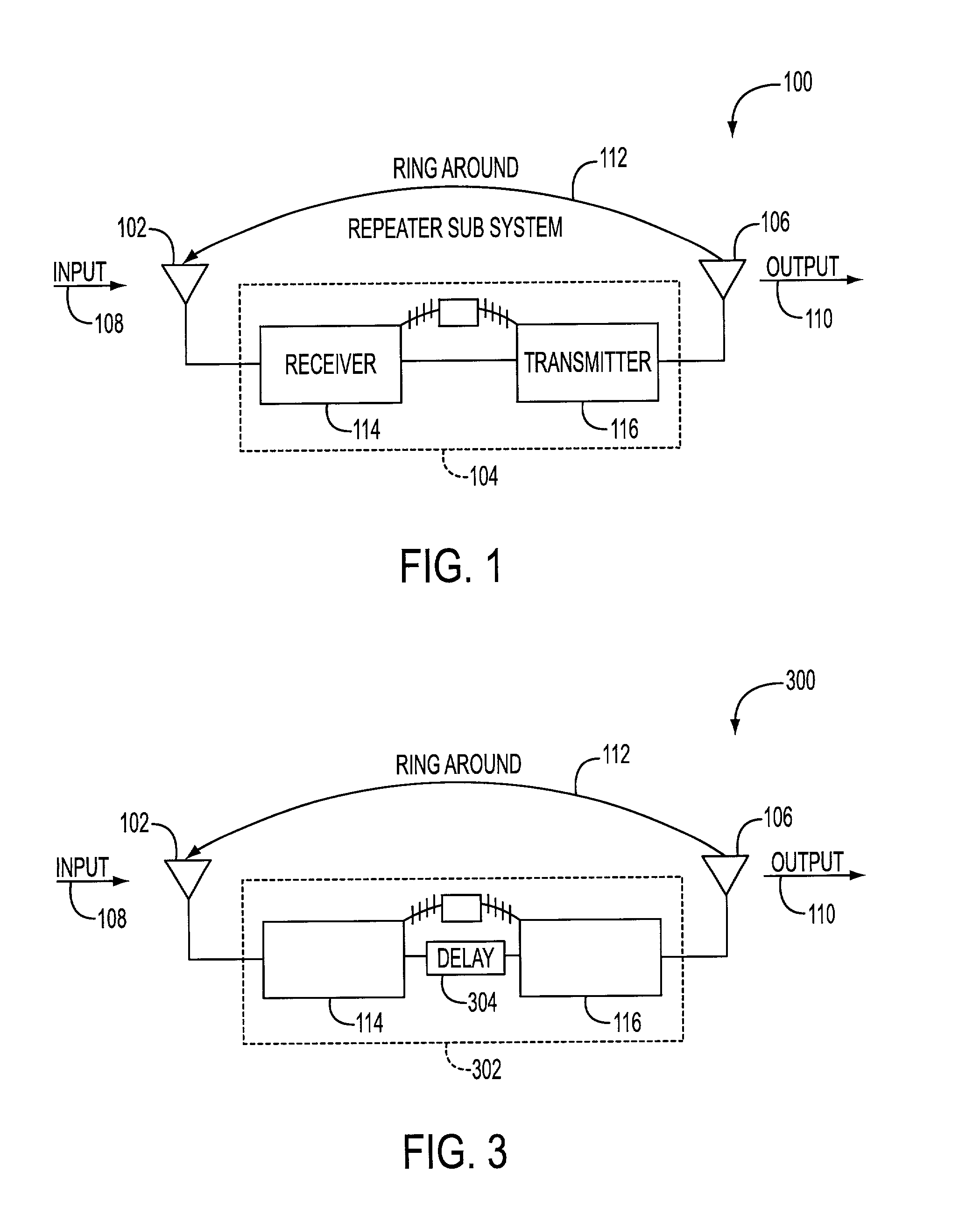
Typically, ring-around is an undesirable phenomenon that creates interference with transponded signals, and / or creates confusing "ghost" echoes of the transponded signals.
The system and method as described in Robinson has limitations that restrict its practical application.
The first limitation deals with the transponder's inability to transpond signals to active radar detectors while in the calibration mode.
On the other hand, for craft that travel at velocities an order of magnitude faster such as aircraft, such times for radar "black-outs" are critical and may be unacceptable.
The second limitation of Robinson's system that restricts its practical application deals with effects of time varying physical quantities such as temperature, pressure, stress, strain and the like, on the transponder.
Specifically, any subsequent change in temperature, pressure, stress, strain and the like, will result in a further unknown and undeterminable inherent delay.
As such, unless a transponder in accordance with the teaching of Robinson is constantly calibrated, then the true, real-time, delay of the system cannot be realized.
However, if a transponder in accordance with the teaching of Robinson is constantly calibrated, then it would never transpond because it is unable to transpond during a calibration mode.
The third limitation of Robinson's system that restricts its practical application deals with problems associated with minute inherent delays in the transponder.
Specifically, if a detected inherent delay in the transponder is smaller than the pulse width of the calibration pulse, the method / system will be unable to determine the amount of the delay.

Method used


Image

  • Self calibration of transponder apparatus
  • Self calibration of transponder apparatus
  • Self calibration of transponder apparatus

Examples


Embodiment Construction

[0038] In the following description, for the purposes of explanation, numerous specific details are set forth in order to provide a more thorough understanding of the present invention. It will be apparent, however, to one skilled in the art that variations of the embodiments disclosed herein are possible.

[0039] FIG. 1 illustrates an exemplary embodiment of a transponder in accordance with the present invention. The transponder 100 includes a receiving antenna 102 for receiving input signals 108 from a radar (not shown), a repeater subsystem for processing the input signals 108, and an output antenna 106 for transmitting output signals 110 (i.e., return signals) back to the radar (not shown). In the exemplary embodiment, the repeater subsystem 104 includes a receiver 114 and a transmitter 116. It is noted that the repeater subsystem may take many various forms, or may be incorporated as part of a system. For the purposes of the present invention, the essential components of the repe...


PUM


Abstract

A method and apparatus is provided for remotely and constantly calibrating a transponder by using the ring around phenomenon. A number of different time varying physical quantities, such as for example temperature, signal level, noise, transmission line flex, frequency, and general operational effects, affect the inherent delay in transponders on a time varying basis. The invention relies on a the ring around phenomenon to produce pulse doublets, wherein the distance between the pulses in the pulse doublets correspond to the instantaneous delay in the transponder. The system is configured so that instantaneous variation in the transmission delay is detected and recognized on a pulse by pulse basis and transmitted to the interrogation device, which then functions to calculate the actual delay. Normal operation of the transponder is not affected by the continuous calibration method, and therefore a special calibration mode is not required.

Description

I. FIELD OF INVENTION[0001] This invention relates generally to an apparatus for determining an inherent delay in a transponder, wherein the delay corresponds to various physical quantities. More particularly, the invention concerns a method and apparatus for determining the inherent delay of a transponder on a pulse-by-pulse basis such that variations in the delay, which occur over the course of operation due to variations in various physical quantities such as temperature, pressure, stress, strain and the like, are immediately known. In addition, the method and apparatus of the present invention allow for determination of the transponder delay without interruption of the normal operation of the transponder device.II. BACKGROUND OF THE INVENTION[0002] At the most fundamental level, radar systems depend on measuring the time delay between a transmitted and a subsequently received signal. The necessary accuracy for the measurement of this delay can be in the sub-microsecond range, an...

Claims


Application Information

Patent Timeline
Patent Type & Authority Applications(United States)
IPC IPC(8): G01S7/40G01S13/76
CPCG01S13/767G01S7/4017
Inventor MORCHEL, HERMAN G.KOCIAN, DONALD J.DIECKE, DIETRICH W.
Owner ITT DEFENSE & ELECTRONICS
Why Eureka
Try Eureka