
Optical fiber grating coder for use in optical code division multiple access, fabricating method and apparatus therefor

a technology of optical fiber grating and optical code, which is applied in the field of optical grating coder, can solve the problems of plurality of phase masks and the conventional fabrication process of chirped optical fiber grating coders, and achieve the effect of reducing the number of phase masks

Inactive Publication Date: 2002-12-12
KOREA INST OF SCI & TECH
View PDF1 Cites 11 Cited by
  • Summary
  • Abstract
  • Description
  • Claims
  • Application Information

AI Technical Summary

Problems solved by technology

Consequently, there are some drawbacks that the conventional fabrication process of the chirped optical fiber grating coder takes much time and a plurality of phase masks is necessary.

Method used


Image

  • Optical fiber grating coder for use in optical code division multiple access, fabricating method and apparatus therefor
  • Optical fiber grating coder for use in optical code division multiple access, fabricating method and apparatus therefor
  • Optical fiber grating coder for use in optical code division multiple access, fabricating method and apparatus therefor

Examples


Embodiment Construction

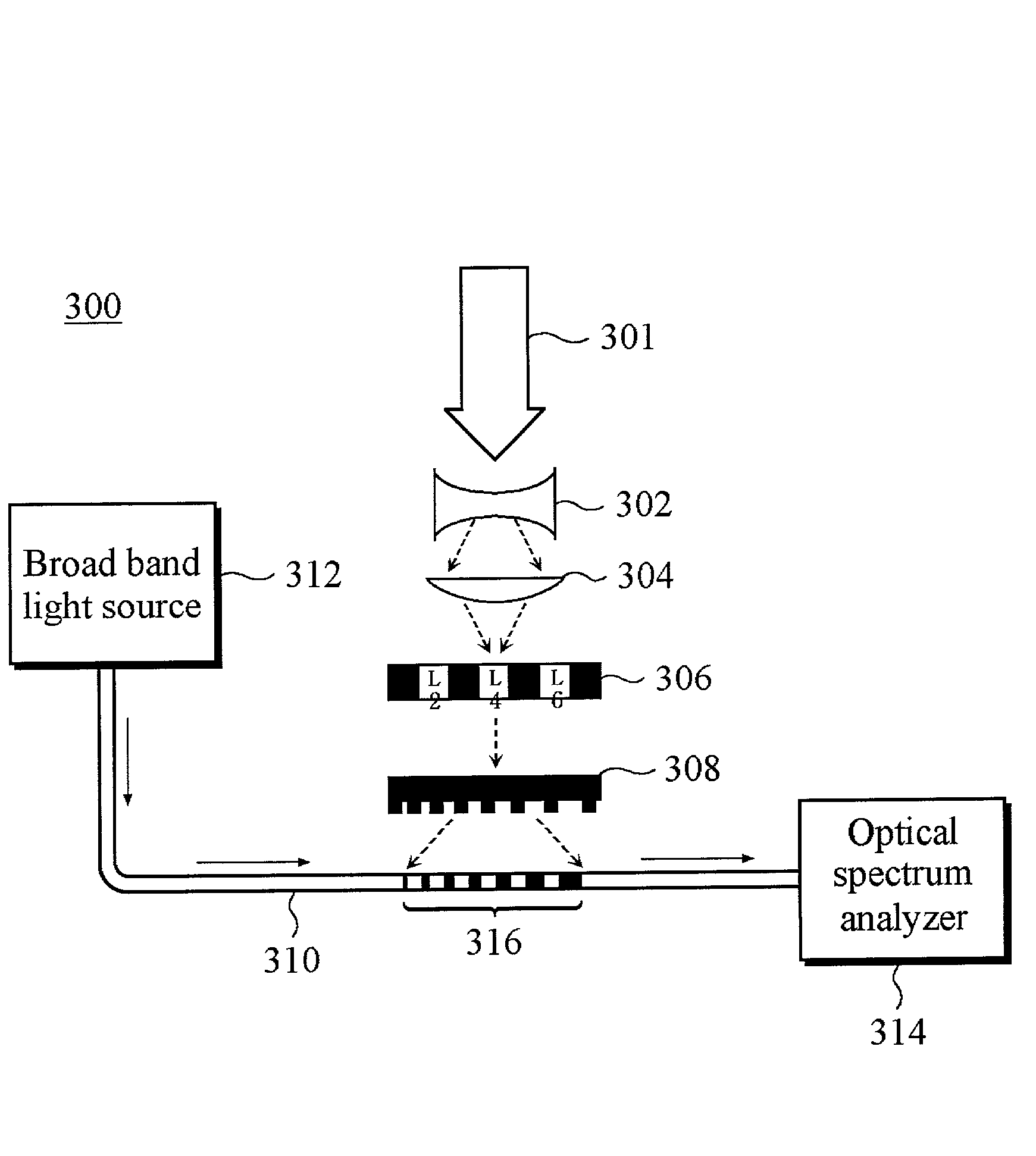
[0028] FIG. 3 illustrates an apparatus for fabricating a chirped optical fiber grating coder in accordance with the present invention. The apparatus 300 of FIG. 3 comprises a light source 301 emitting an ultraviolet light beam, a concave lens 302, a convex lens 304, an amplitude mask 306, a chirped phase mask 308, and a single-mode optical fiber 310 for use in the telecommunication system.

[0029] Similar to the prior art described above, a broadband light source (BBS) 312 and an optical spectrum analyzer 314 are provided for measuring the transmission characteristics of a chirped optical fiber grating coder 316 formed in a core of the fiber 310. Specifically, an Erbium-doped optical amplifier may be used as the BBS 312. The optical spectrum analyzer 314 is commercially available.

[0030] The chirped phase mask 308 of FIG. 3 is defined by three characteristics that are the length, range, chirping rate of it. According to predetermined codewords, the chirped phase mask 308 is used as wav...


PUM


Abstract

An optical fiber grating coder includes predetermined codewords imprinted into an optical fiber in the form of a plurality of striations through an apparatus including a light source, an amplitude mask, and a phase mask. A fabrication method of the optical fiber grating coder includes providing a light source, an amplitude mask designed for predetermined codewords, a phase mask, and an optical fiber; exposing the optical fiber; and forming an optical fiber grating coder into the optical fiber. A fabrication apparatus of the optical fiber grating coder includes a light source; an amplitude mask designed for predetermined codewords; a phase mask; and an optical fiber where the optical fiber grating coder is to be formed.

Description

[0001] 1. Field of the Invention[0002] The present invention relates to an optical grating coder; and, more particularly, to a chirped optical fiber grating coder implementing predetermined codewords for use in an OCDMA (Optical Code Division Multiple Access) system, a fabricating method and an apparatus therefor.[0003] 2. Description of the Related Art[0004] An optical fiber grating is generally fabricated by using the refractive index variation of a core of an optical fiber when a core doped with Germanium (Ge) is exposed to an ultraviolet light. A short-period optical fiber grating is typically referred to an optical fiber grating. The short-period optical fiber grating has a grating period of 0.5 .mu.m, approximately, and a length less than 10 mm. The short-period optical fiber grating may be used as a reflection filter for filtering light wavelengths, external reflection mirrors of an optical fiber laser and a semiconductor laser, an optical fiber grating Fabry-Perot etalon, an...

Claims


Application Information

Patent Timeline
Patent Type & Authority Applications(United States)
IPC IPC(8): G02B6/02G02B5/18G02B6/34H04J14/00
CPCG02B6/02085G02B6/02138H04J14/005G02B6/2932G02B6/02142G02B5/18
Inventor KOO, HYUN DEOKLEE, SANG BAECHOI, SANG SAM
Owner KOREA INST OF SCI & TECH
Learn More