Method and apparatus for boundary layer reattachment using piezoelectric synthetic jet actuators

a synthetic jet actuator and boundary layer technology, applied in the field of aerodynamics, can solve the problems of increasing the maximum cruising speed of an aircraft, heavy and expensive production and maintenance of flap arrangements, and not focusing on the reduction of drag and postponemen

Inactive Publication Date: 2002-12-26
AUBURN UNIV
View PDF0 Cites 61 Cited by
  • Summary
  • Abstract
  • Description
  • Claims
  • Application Information

AI Technical Summary

Problems solved by technology

These flap arrangements, however, typically are heavy and expensive to produce and maintain.
In addition, decreased drag increases the maximum cruising speed of an aircraft.
To date,

Method used


Image

  • Method and apparatus for boundary layer reattachment using piezoelectric synthetic jet actuators
  • Method and apparatus for boundary layer reattachment using piezoelectric synthetic jet actuators
  • Method and apparatus for boundary layer reattachment using piezoelectric synthetic jet actuators

Examples


Embodiment Construction

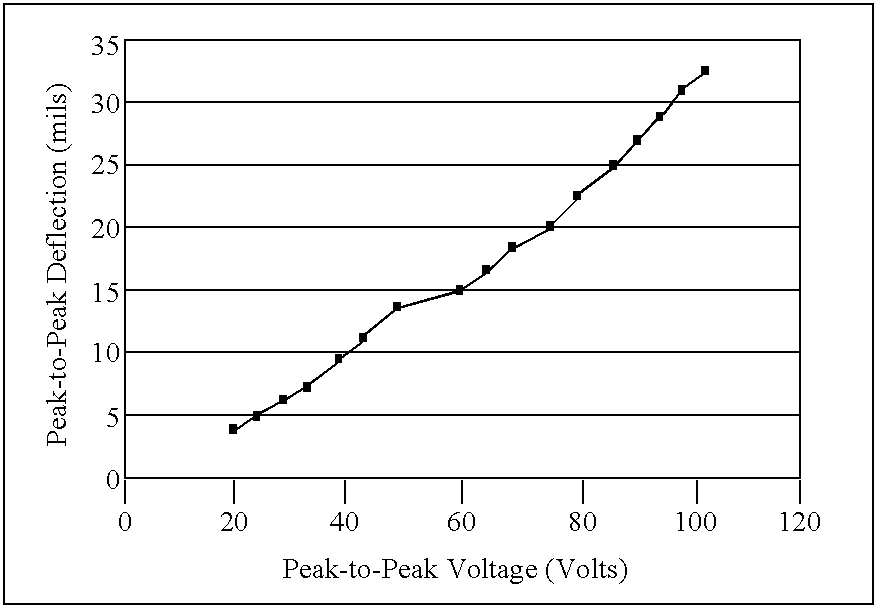
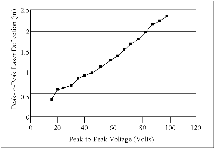
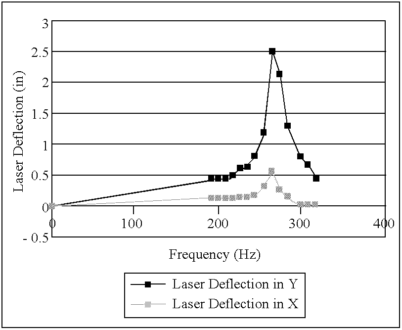
[0026] A wing section incorporating certain aspects of the present invention was fabricated and studied. The following outlines the design, manufacturing, and testing of piezoelectric synthetic jet actuators (PJets) in an associated wing section used to reattach the boundary layer. In order to achieve boundary layer reattachment the PJets were mounted inside a 6 inch wide by 12 inch long NACA 0012 airfoil. The air flowing over the upper surface of the airfoil was ingested through inlet slots located at 50% and 75% chord and then expelled tangential to the surface through outlet slots located at 30% chord. The outlet slot was covered with a fiberglass flap to direct the flow. By running the PJets at 100 Volts AC peak-to-peak, a resonance frequency was reached at 420 Hz, which allowed the PJets to ingest the maximum amount of air possible. When the wing was tested in the wind tunnel at various angles of attack it was observed, through the use of titanium tetrachloride flow visualizati...


PUM


Abstract

A method and apparatus for active boundary layer control on an aerodynamic surface. One or more piezoelectric synthetic jet actuators operate as a boundary layer pump to ingest fluid along the surface of an aerodynamic object and discharge fluid tangentially to the fluid flow along the surface and/or at the trailing edge of the object to reduce drag and delay stall.

Description

[0001] This application claims the benefit of U.S. Provisional Patent Application Serial No. 60 / 278,790, filed Mar. 26, 2001, the entirety of which is hereby incorporated herein by reference for all purposes.[0002] 1. Field of the Invention[0003] The present invention relates generally to the field of aerodynamics, and more particularly to methods and systems for improving aerodynamic performance through active boundary layer control.[0004] 2. Description of Related Art[0005] Considerable research has been conducted in the field of aerodynamics toward reducing drag and delaying stall. Delaying stall allows an airplane to fly more slowly at a given angle of attack or to fly at a higher angle of attack for a given speed. A lower stall speed increases the factor of safety for any takeoff or landing, and also allows for shorter takeoffs and landings. Shorter takeoff and landing requirements may allow smaller airports to accommodate larger aircraft, thereby decreasing the traffic around ...

Claims


Application Information

Patent Timeline
IPC IPC(8): B64C21/02B64C23/00
CPCB64C21/025B64C23/005B64C2230/18B64C2230/04B64C2230/12Y02T50/166Y02T50/10
Inventor BARRETT, RONALD M.REASONOVER, CHRISTOPHERCORPENING, JEREMY
Owner AUBURN UNIV
Why Eureka
Try Eureka