Stacked GBIC guide rail assembly

a stacked, guide rail technology, applied in the direction of fixed connections, coupling device connections, instruments, etc., can solve the problem of a large amount of space on the print circuit board for a multi-transceiver configuration

Inactive Publication Date: 2002-12-26
HON HAI PRECISION IND CO LTD
View PDF0 Cites 90 Cited by
  • Summary
  • Abstract
  • Description
  • Claims
  • Application Information

AI Technical Summary

Problems solved by technology

Though this design presents a low-profile merit, a great amount of space of the print circuit board is required for a multi-transceiver configuration.

Method used


Image

  • Stacked GBIC guide rail assembly
  • Stacked GBIC guide rail assembly
  • Stacked GBIC guide rail assembly

Examples


Embodiment Construction

[0017] Reference will now be made to the drawings to describe the present invention in detail.

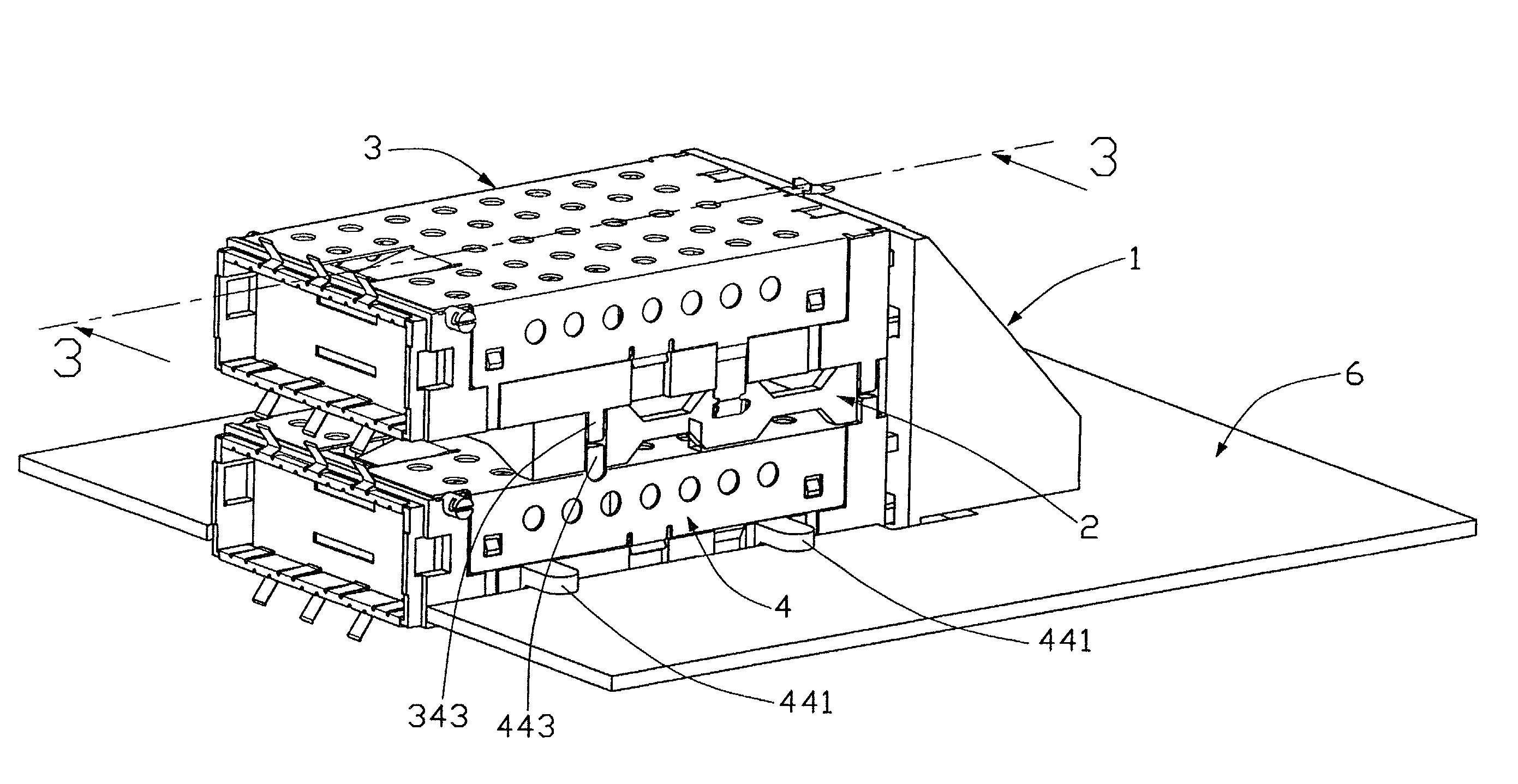
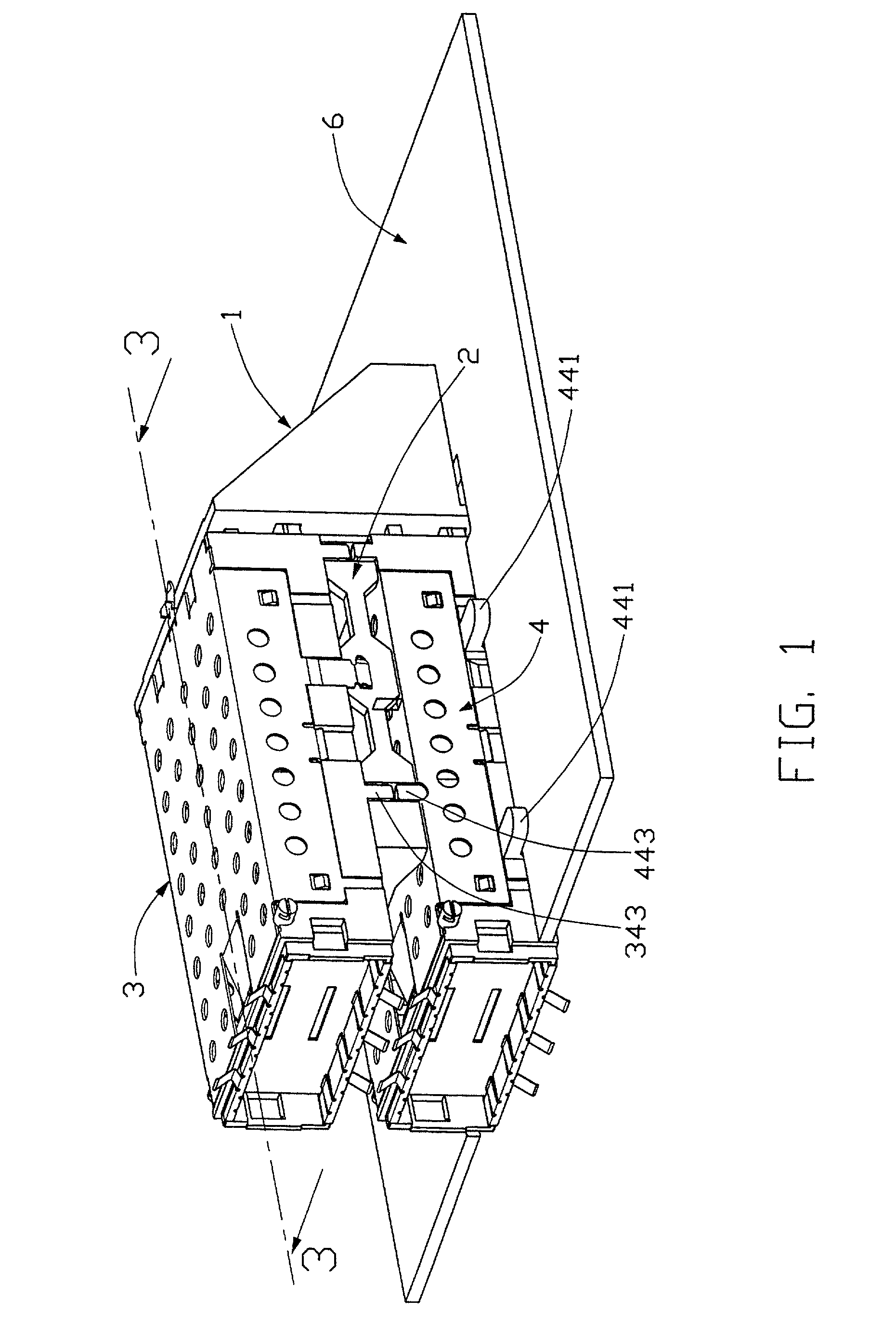
[0018] Referring to the drawings, and particularly to FIG. 1, a stacked GBIC guide rail assembly in accordance with the present invention comprises a raiser 1, a spacer 2, an upper guide rail 3, and a lower guide rail 4. The upper guide rail 3 and the lower guide rail 4 are capable to receive and accommodate transceivers therein. The upper and lower guide rail 3, 4 are engaged with the raiser 1 and spaced by the spacer 2 and the lower guide rail 4 is mounted to a printed circuit board 6.

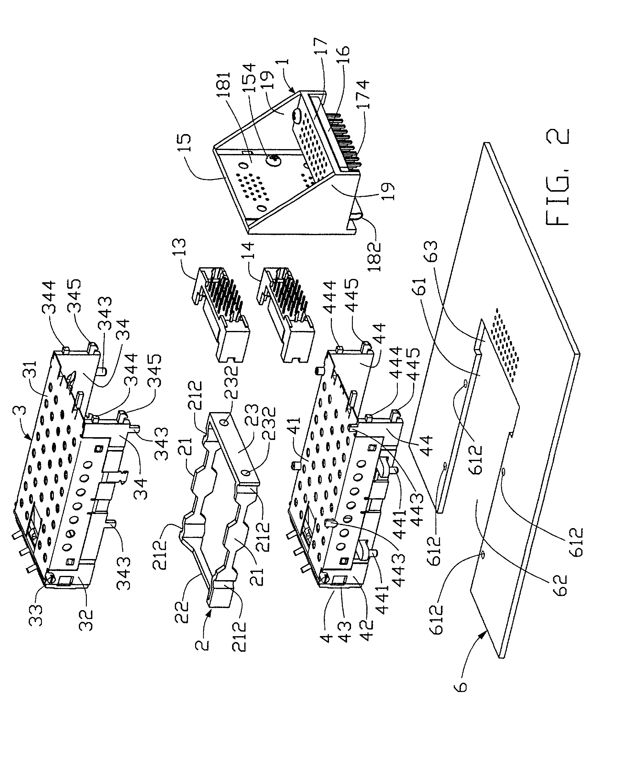
[0019] Turning to FIGS. 2 and 3, the raiser 1 comprises a first wall 15 and two parallel sidewalls 19 extending from the first wall 15. A base 17 having a plurality of contact pins 174 soldered to the printed circuit board 6 is formed between the sidewalls 19.

[0020] Also referring to FIG. 4, an upper SCA2 receptacle 13 and a lower SCA2 receptacle 14 are attached to the first wall 15 of the raiser 1. Two pair...


PUM


Abstract

A stacked Gigabyte Interface Converter (GBIC) guide rail assembly for removable optoelectronic modules includes a raiser mounted on a circuit board, a plurality of guide rails fixed to the raiser, and a plurality of spacers spacing the guide rails from each other. The guide rails receive and accommodate transceivers therein for forming a dense arrangement of the transceivers. The lowest guide rail is mounted and supported on the circuit board.

Description

[0001] 1. Field of the Invention[0002] The present invention relates generally to an optoelectronic module guide system, and particularly to a stacked gigabyte interface converter (GBIC) guide rail assembly for removable optoelectronic modules, such as transceiver modules that interface with peripheral devices.[0003] 2. Description of Related Art[0004] As known in the art, it is desirable to optimize multitransceiver configuration in order to increase the port density associated with the network connection, such as switch boxes, wiring closets, and computer I / O.[0005] An equipment in the prior art for accommodating optoelectronic transceivers therein generally has cables connected to the equipment. As disclosed in U.S. Pat. No. 5,373,421, an assembly for accommodating fiber optic transceivers comprising a front plate having a plurality of holes, a plurality of accommodating members attached to the rear of the front plate and extending vertically from each of the plurality of holes. ...

Claims


Application Information

Patent Timeline
Patent Type & Authority Applications(United States)
IPC IPC(8): G02B6/38H01R12/50H01R13/658
CPCG02B6/3897H01R2201/06H01R23/6873H01R13/65802H01R12/716H01R12/724H01R13/6582H01R13/659
Inventor HWANG, JENQ-YIH
Owner HON HAI PRECISION IND CO LTD
Why Eureka
Try Eureka