Cable location system using magnetic induction

a magnetic induction and location system technology, applied in the direction of electric/magnetic detection for transportation, using reradiation, instruments, etc., can solve the problems of direct connection creating a potential shock hazard, interference with signals or conversations, and loss, theft or destruction

Inactive Publication Date: 2003-01-02
3M INNOVATIVE PROPERTIES CO
View PDF0 Cites 23 Cited by
  • Summary
  • Abstract
  • Description
  • Claims
  • Application Information

AI Technical Summary

Problems solved by technology

Above-ground marking devices may be installed immediately after the conduit is buried, but they are often lost, stolen, or destroyed after a short period of use.
It is possible to directly connect the signal source to the cable where a bare wire is exposed, but this is undesirable as it may result in interference with signals or conversations on the cable.
Moreover, direct connection creates a potential shock hazard, and is further unsuitable in instances where no bare wire is exposed.
The most significant disadvantage in the use of a tracing wire or conductive conduit to radiate a locator signal, is that a receiver cannot distinguish the trace conductor from any other conductor in the vicinity which may be carrying the same trace current.
Disconnecting the cable shields at the pedestal before applying the locating signal is certain...

Method used


Image

  • Cable location system using magnetic induction
  • Cable location system using magnetic induction
  • Cable location system using magnetic induction

Examples


Embodiment Construction

)

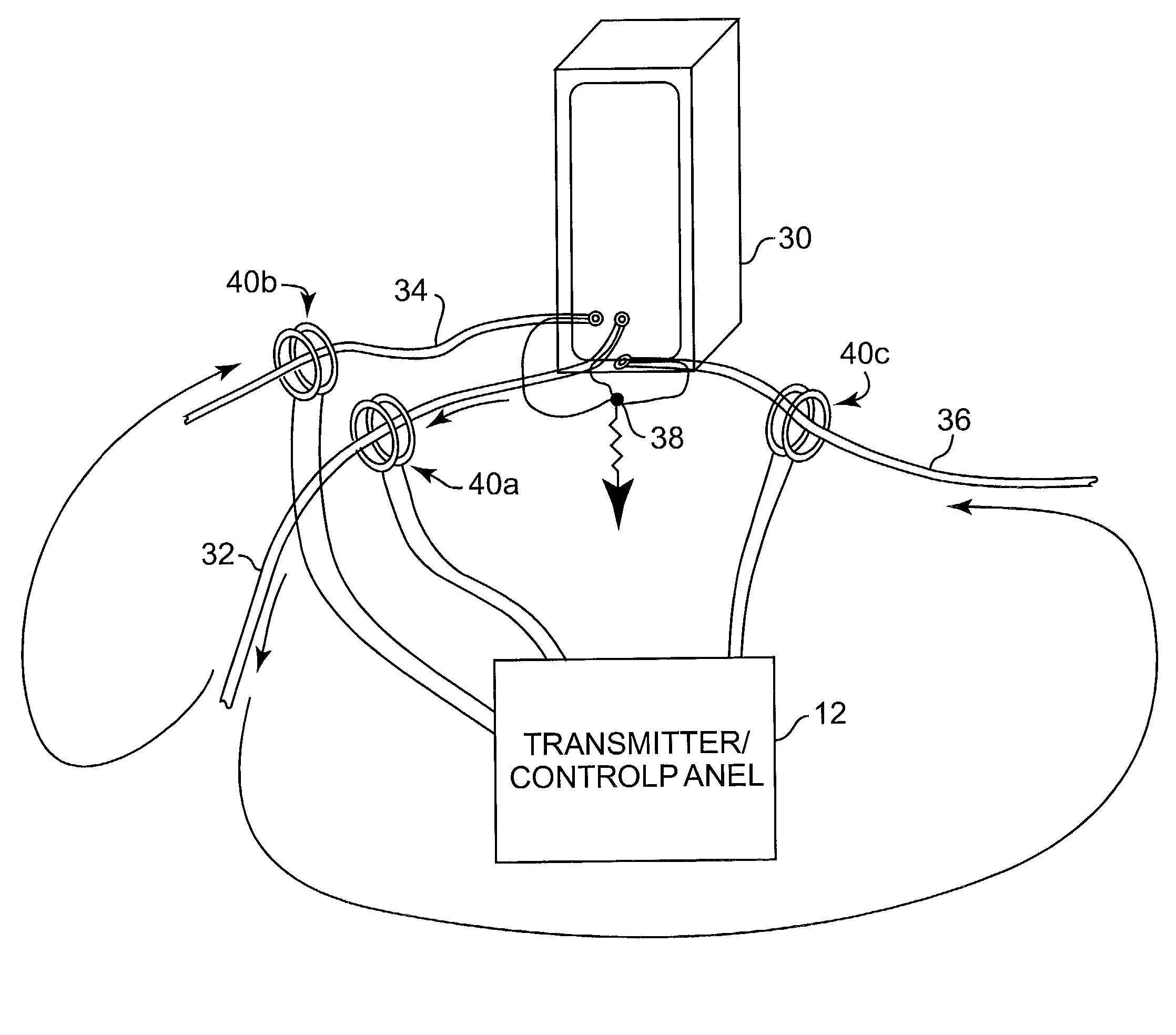
[0029] The present invention is directed to a method for inserting a high impedance value in-series with a single conductor (or multiple conductors) using magnetic induction, preferably by clamping a fully isolated device around the conductor without making a metallic connection to the conductor. Furthermore, the induced impedance can be varied in magnitude and phase by a control circuit, as explained further below, which adds a programmability feature. When the isolation required is only for a single known frequency rather than a band of frequencies, then higher isolation levels can be obtained and the system is more stable. The description hereafter generally relates to the single-frequency isolation or cancellation configuration. The term "clamp" as used herein refers to electrical clamping of the conductor, and not necessarily to a physical clamping.

[0030] If a toroid-shaped small magnetic core is place around a conductor, it will make a 1-turn toroid inductor of inductance in ...


PUM


Abstract

A method of electronically isolating a conductor by sensing a current signal in the conductor, adjusting the current signal to yield an adjusted signal, and applying the adjusted signal to the conductor to oppose the current signal. Amplifying the signal, as well as phase-shifting the signal may adjust the current signal. The current signal may be sensed using magnetic induction, and the adjusted signal applied to the conductor using magnetic induction as well. The method is carried out using a clamping device that can further evaluate an environment of the conductor, by randomly changing a magnitude and phase of a test signal applied to the conductor, and examining a received signal in response to the changes. A tracking error in the adjusted signal can be handled by predicting a next required phase shift. Prediction coefficients can be calculated utilizing a least means square algorithm. The invention is particularly applicable to the location of obscured (e.g., buried) conductors, and can be incorporated into a cable locator system that applies a trace signal to the target cable to be located. When this trace signal bleeds onto adjacent cables, the clamping devices of the present invention can be used to electronically isolate those cables, i.e., reduce or eliminate unwanted currents arising from coupling with the trace signal. A conventional receiver can then be used to trace the path of the target cable without interference from the nearby cables.

Description

[0001] The present application is related to co-pending and commonly assigned application entitled "METHOD FOR INDUCED-IMPEDANCE ISOLATION USING MAGNETIC INDUCTION" filed on the same date and by the same inventors, which is hereby incorporated by reference.[0002] 1. Field of the Invention[0003] The present invention generally relates to systems and devices for inserting a variable impedance in a conductor, and more particularly to a method and apparatus for locating an obscured (buried) conductor which acts as an antenna to radiate a location signal, wherein the method and apparatus isolate unwanted interference from adjacent conductors.[0004] 2. Description of the Related Art[0005] Buried conduits are employed for supplying a wide variety of utilities, including pipelines for gas, water and sewage, and cables for telephone, power and television. It often becomes necessary to locate defective or damaged cables, pipes, etc., in order to repair or replace them. Conversely, it is impor...

Claims


Application Information

Patent Timeline
IPC IPC(8): G01V3/10G01V3/15
CPCG01V3/104G01V3/15
Inventor DOANY, ZIYAD H.MCCAMMON, ROY B.
Owner 3M INNOVATIVE PROPERTIES CO
Why Eureka
Try Eureka