Link adaptation for MIMO transmission schemes

a transmission scheme and link technology, applied in the field of link adaptation for mimo transmission schemes, can solve the problem that the transmission potential of the mimo channel might not be fully exploited in most cases, and achieve the effect of reducing the number of strata, substantial performance gain, and small potential rate of one or more strata

Active Publication Date: 2003-01-02
TELEFON AB LM ERICSSON (PUBL)
View PDF5 Cites 279 Cited by
  • Summary
  • Abstract
  • Description
  • Claims
  • Application Information

AI Technical Summary

Benefits of technology

0031] Depending on the channel conditions, it could be that the potential rate of one or more strata is very small. Then, it is usually advantageous to reduce the number of strata, i.e. the number of independent strata. Therefore it is another object of the invention to present a solution that adapts appropriately the transmitted signal in case of switching off strata while all transmit antennas are still in use.
0032] To optimize the exploitation of the MIMO channel the link quality of each subsignal is determined in the receiver, information of each subsignal is transmitted to the transmitter via the feedback channel and that in the transmitter properties of the subsignals are controlled by the feedback information. As MIMO transmission offers a substantial performance gain when the channel is fed appropriately the way of link adaptation proposed here tries to exploit a big portion of this potential also in practice.

Problems solved by technology

That means if the parameters assigned to all layers are identical the transmission potential of the MIMO channel might not be fully exploited in most of the cases.
While for V-BLAST in HSDPA, switching off of antennas is considered as one ingredient in the link adaptation concept, for other transmission techniques like MSSTC, there are not yet such proposals available.

Method used


Image

  • Link adaptation for MIMO transmission schemes
  • Link adaptation for MIMO transmission schemes
  • Link adaptation for MIMO transmission schemes

Examples


Embodiment Construction

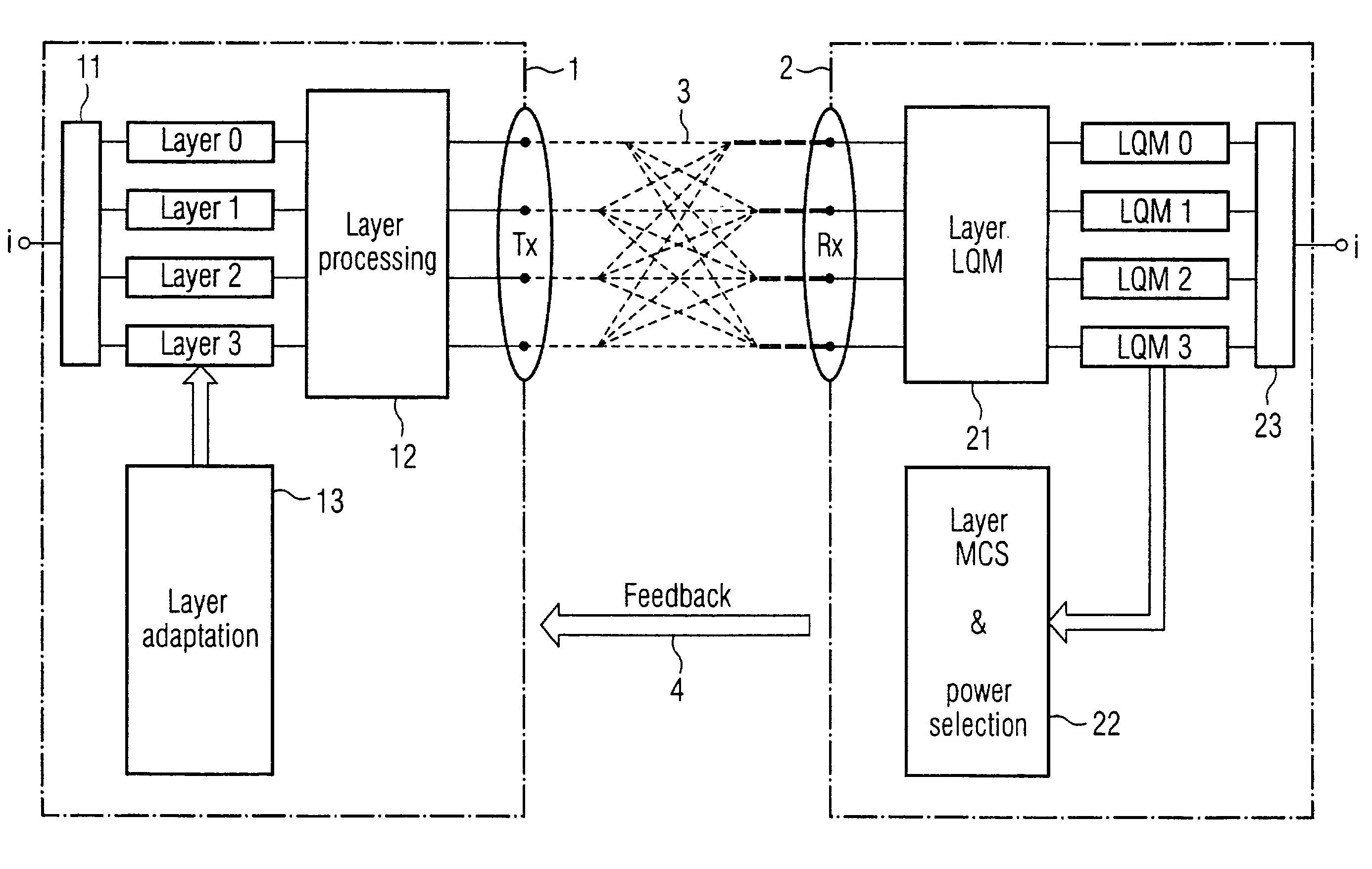
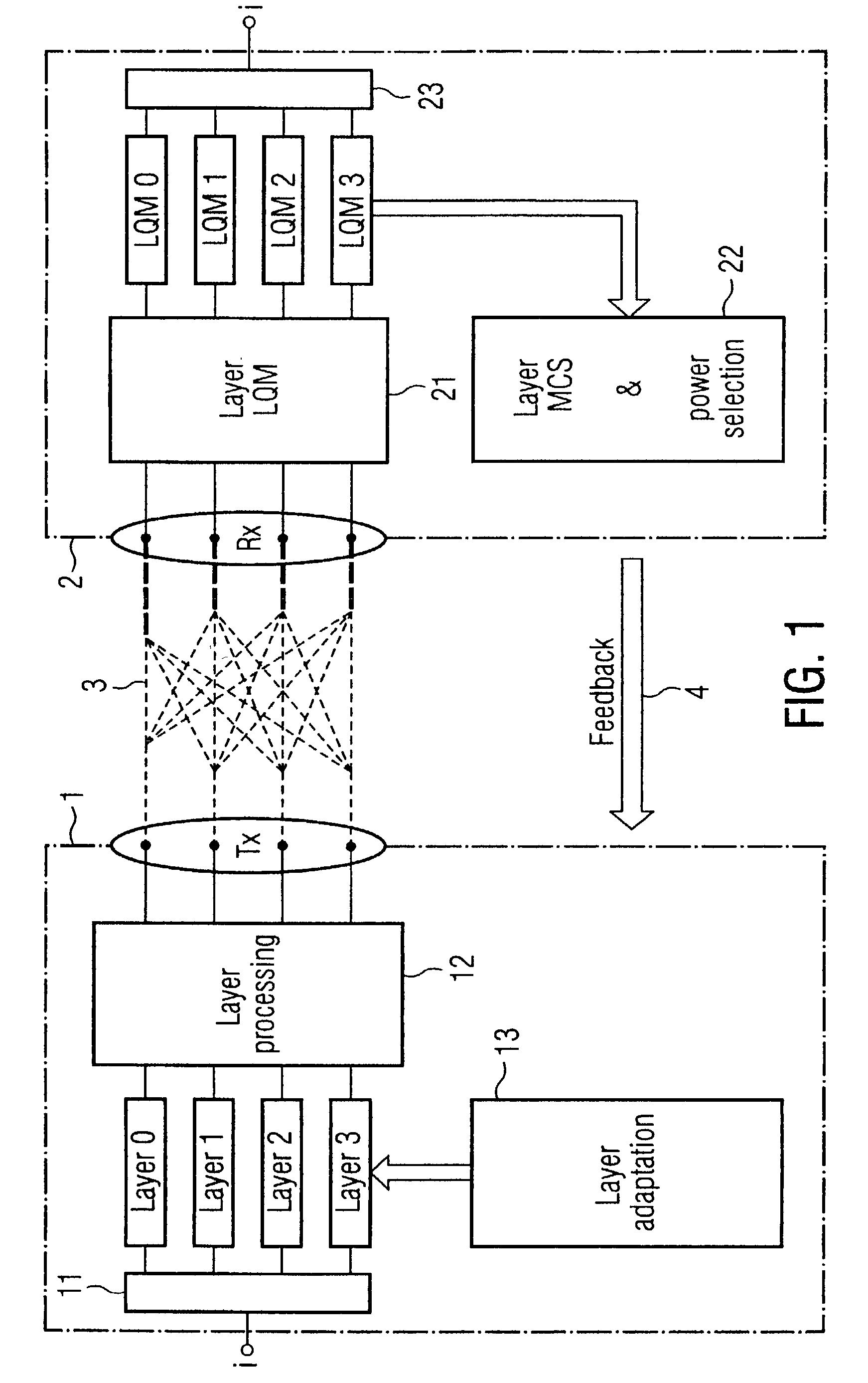
[0043] FIG. 1 shows a MIMO communication system with a transmitter 1 and a receiver 2. In this embodiment the transmitter 1 provides four transmit antennas and the receiver 2 also provides four receive antennas. Payload information i is split in the transmitter by a demultiplexer 11 into four subsignals which are also called Layer 0, Layer 1 Layer 2 and Layer 3. The demultiplexer can be controlled in a way that the data rate of each subsignal may be chosen different from the data rates of the other subsignals. The subsignals are processed by a layer processing unit 12 to achieve the desired MIMO properties. The subsignals are transmitted to the receiver 2 whereby they are subjected to a MIMO channel. In the receiver 2 the different layers are decoded and the link quality of each received subsignal (each layer) is determined by a layer link quality means 21. In this embodiment the link quality information is evaluated in the receiver in an evaluation unit 22 and control information i...


PUM


Abstract

MIMO transmission methods are applied to communicaiton systems in which a transmitter has more than one transmit antenna and a receiver has more than one receive antenna. Information to be transmitted is divided into a plurality of subsignals according to the number of used transmit antennas and each subsignal is processed separately before it is emitted by the respective transmit antenna. In the receiver the different receive signals are processed thus that subsignals are detected and decoded and the contribution of each detected and decoded subsignal is subtracted from the receive signals and whereby a feedback channel from receiver to transmitter is used to send control information to the transmitter depending on the receive situation. In order to optimize the usage of the MIMO channel the invention proposes the in the receiver the link quality of each subsignal is determined and information of each subsignal is transmitted to the receiver via the feedback channel and that in the transmitter properties of the subsignals are controlled by the link quality information.

Description

[0001] The present invention relates to a wireless communication system for transmitting information between a transmitter having more than one transmit antenna and a receiver having more than one receive antenna, whereby information to be transmitted is divided into a plurality of subsignals. Each subsignal in such a system is processed separately before it is emitted by the transmit antenna. In the receiver adapted for such a system the receive signal is processed thus that subsignals are detected and decoded. The contribution of each detected and decoded subsignal is subtracted from the receive signal. A feedback channel from receiver to transmitter is used to send control information to the transmitter depending on the receive situationDESCRIPTION OF THE PRIOR ART[0002] One method to efficiently utilise the available transmission potential of wireless communication channels is to use link adaptation (LA). Thereby, the transmitter has knowledge of one or more channel parameters r...

Claims


Application Information

Patent Timeline
Patent Type & Authority Applications(United States)
IPC IPC(8): H04B7/005H04B7/04H04B7/0417H04B7/0426H04B7/06H04B7/08H04L1/00H04L1/06H04L1/12H04L12/28H04L12/56
CPCH04B7/0417H04B7/0443H04B7/0613H04B7/0632H04B7/0837H04L1/0003H04L1/0009H04L1/0656H04L1/12H04L5/0046H04L25/0208H04L25/0248H04W24/00H04W28/06H04W28/18H04W52/42H04L25/0204
Inventor THIELECKE, JORNWACHSMANN, UDO
Owner TELEFON AB LM ERICSSON (PUBL)
Why Eureka
Try Eureka