High-density disk recording medium having a reflecting surface and manufacturing method thereof

Inactive Publication Date: 2003-01-09
LG ELECTRONICS INC
View PDF7 Cites 8 Cited by
  • Summary
  • Abstract
  • Description
  • Claims
  • Application Information

AI Technical Summary

Problems solved by technology

However, in this case, the objective lens OL will collide with the misplaced HD-DVD 10.
Consequent

Method used


Image

  • High-density disk recording medium having a reflecting surface and manufacturing method thereof
  • High-density disk recording medium having a reflecting surface and manufacturing method thereof
  • High-density disk recording medium having a reflecting surface and manufacturing method thereof

Examples


second embodiment

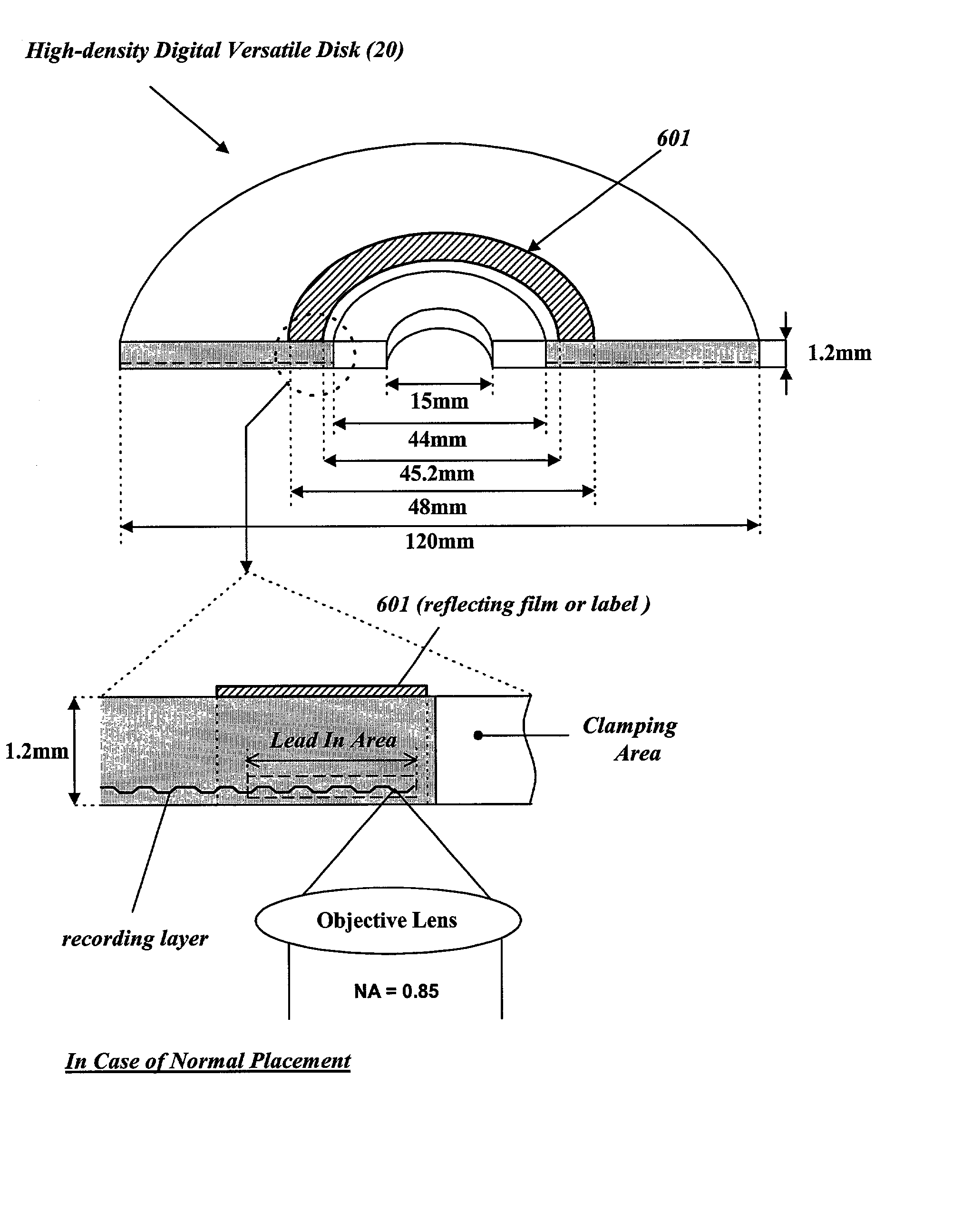
[0038] In the second embodiment, a reflecting film 801 or a reflecting label covers almost entire surface opposite to the recording surface the recording layer is in closer proximity to. The reflecting film 801 or the reflecting label does not cover the clamping area, preferably.

first embodiment

[0039] The same as the first embodiment, if the disk 21 of which one surface has been covered with the reflecting film 801 or the reflecting label as shown in FIG. 8 or 9 is misplaced upside down, its misplacement can be judged from no signal in FES in the process of normal focusing servo operation. Consequently, a collision between the objective lens `OL` and the misplaced disk 21 can be prevented basically.

[0040] Now, it is explained how a high-density disk having a reflecting film or a reflecting label on non-recording surface is manufactured.

[0041] FIG. 10 shows a schematic process of manufacturing a read-only high-density disk having a reflecting film or a reflecting label on entire non-recording surface excluding a clamping area in accordance with the present invention. According to the disk manufacturing process of FIG. 10, a metal master is obtained through a mastering process (S101) using an electroplated glass master on which pit patterns of recorded signals are formed. Se...


PUM


Abstract

The present invention relates to a high-density disk that is structured to prevent a collision of an optical pickup's objective lens with the high-density disk if the disk is placed upside down in a disk device that is able to record and reproduce signals to/from the high-density disk. A high-density disk recording medium according to the present invention has a reflecting thin film or label, formed on a surface opposite to a recording surface, to block a beam incident to an inserted disk not to travel up to a lead-in area, which a disk device tries to read first when a disk is placed, in the event that the inserted disk has been misplaced upside down.

Description

[0001] 1. Field of the Invention[0002] The present invention relates to a high-density disk structure preventing collision of an optical pickup's objective lens with a high-density disk which is placed upside down in a disk device being able to reproduce and record signals from / to a high-density disk such as a high-density digital versatile disk (called "HD-DVD" hereinafter). The present invention further relates to a method of determining whether or not said high-density disk is placed upside down.[0003] 2. Description of the Related Art[0004] A compact disk, usually called "CD", is 1.2 mm in thickness and 120 mm in diameter as shown in FIG. 1. A CD has a center hole of 15 mm diameter and a clamping zone of 44 mm, which encircles the center hole where the clamping zone is clamped by a damper on a spindle or a turntable installed in a disk device.[0005] When a CD is normally placed into a disk device, its recording layer, which has pit patterns, is approximately 1.2 mm from a surfac...

Claims


Application Information

Patent Timeline
IPC IPC(8): G11B7/007G11B7/085G11B7/12G11B7/121G11B23/00G11B23/40
CPCG11B7/08511G11B7/1201G11B7/24053G11B7/24062G11B23/0021G11B23/40G11B7/121
Inventor KIM, JIN YONGPARK, KYUNG CHANKIM, WAE YEUL
Owner LG ELECTRONICS INC
Why Eureka
Try Eureka