Disk device

Inactive Publication Date: 2003-01-16
PANASONIC HEALTHCARE HLDG CO LTD
View PDF2 Cites 4 Cited by
  • Summary
  • Abstract
  • Description
  • Claims
  • Application Information

AI Technical Summary

Benefits of technology

0009] The present invention is made to solve such problems in the prior art, and it is an object of the invention to construct a disk device such as a magnetic hard disk drive at a

Problems solved by technology

However, the following problems exist in such well-known devices.
Due to nonconformity in components and/or assembly, some devices need to be repaired after assembly before being placed on the market.
In this case, since the top cover 13 is not low-priced, there is a problem such that the price of the device is raised.
In addition, since the device has a low profile, screwing margins cannot be provided on the lower surface of the frame body.
Since the frame body 4 and the spindle motor 3 are not low-priced, there is a problem such that the

Method used


Image

  • Disk device
  • Disk device
  • Disk device

Examples


Embodiment Construction

[0052] In the present invention, such problems of the prior art have been solved and in the following, an embodiment thereof will be described.

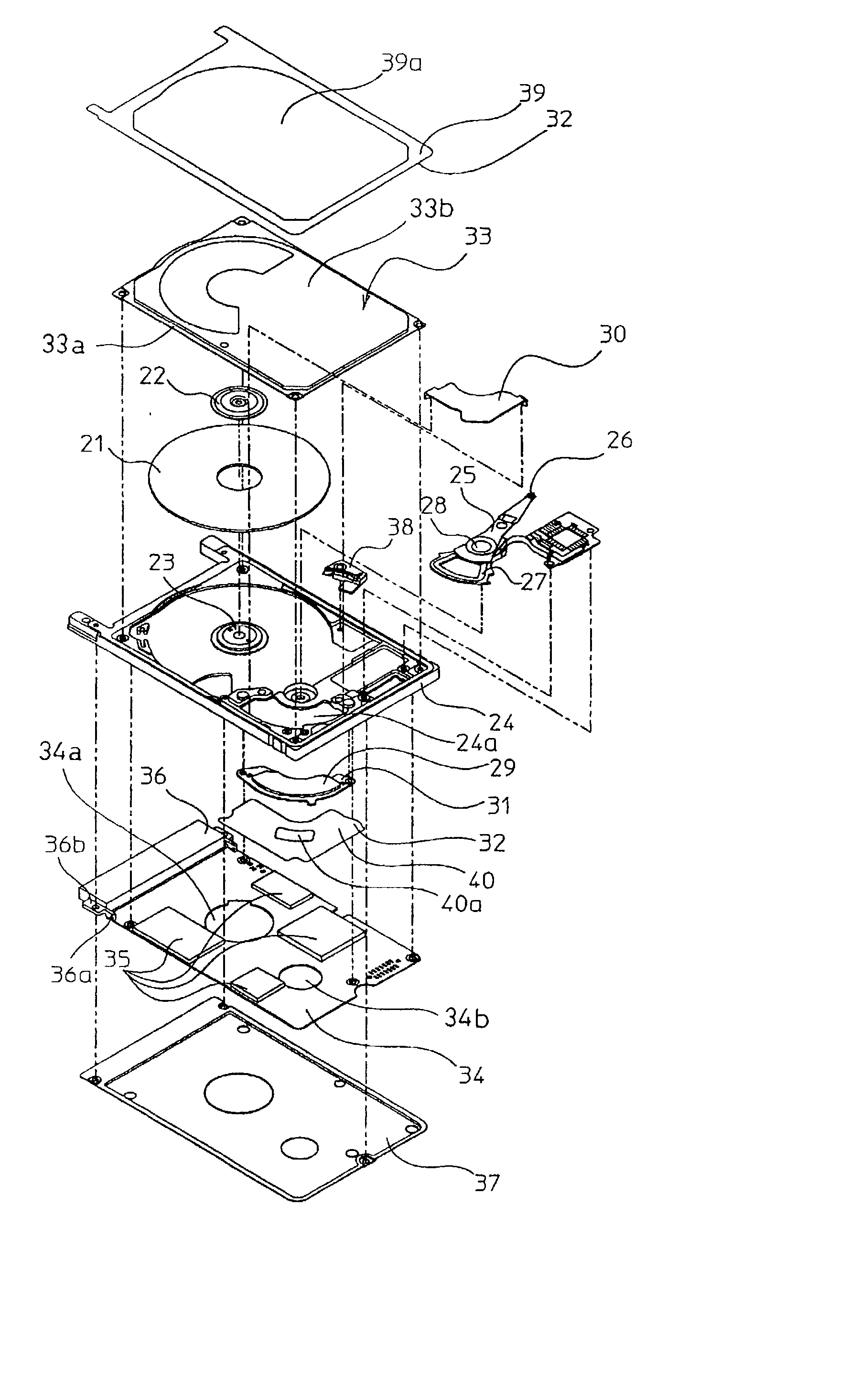
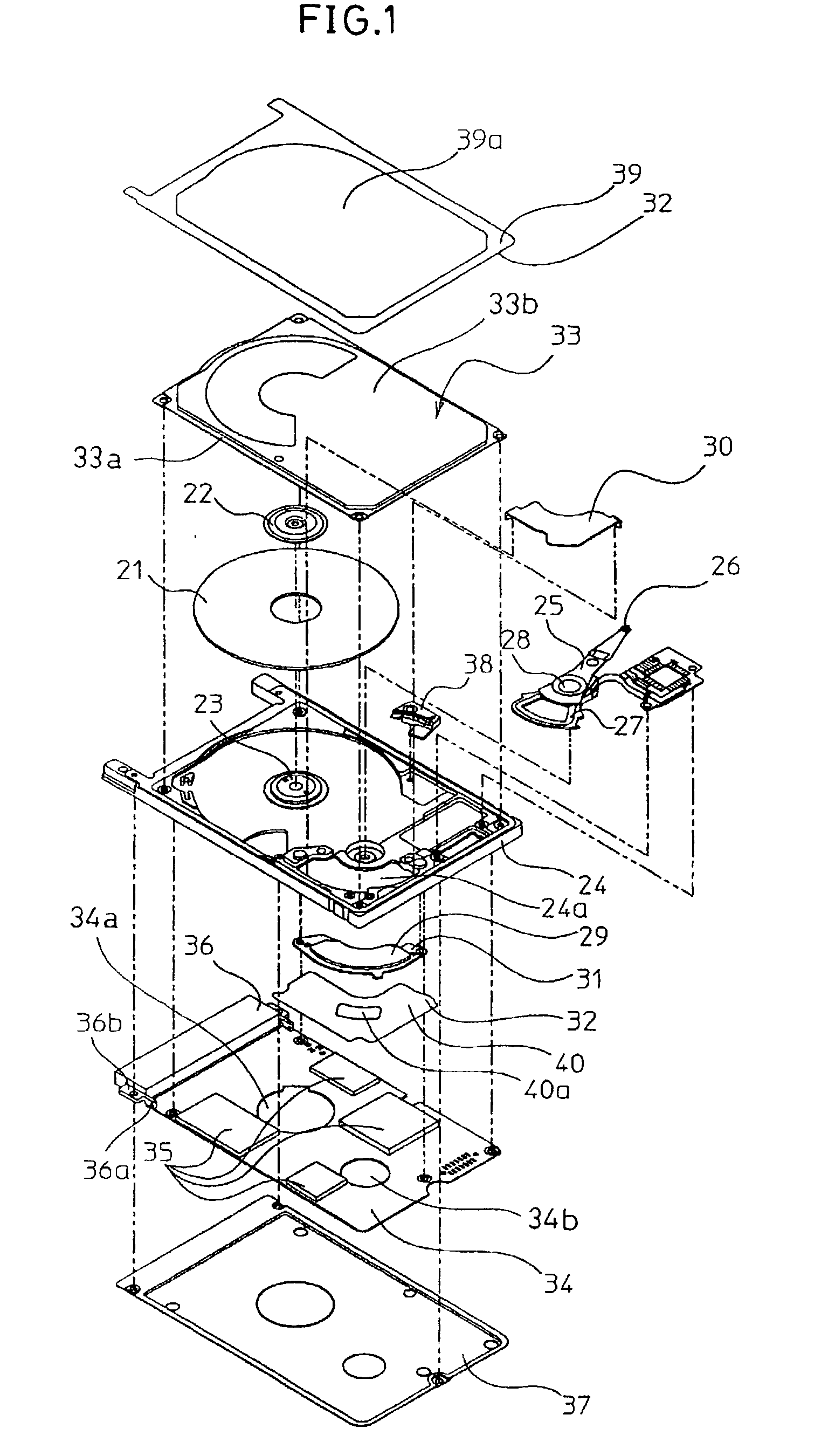
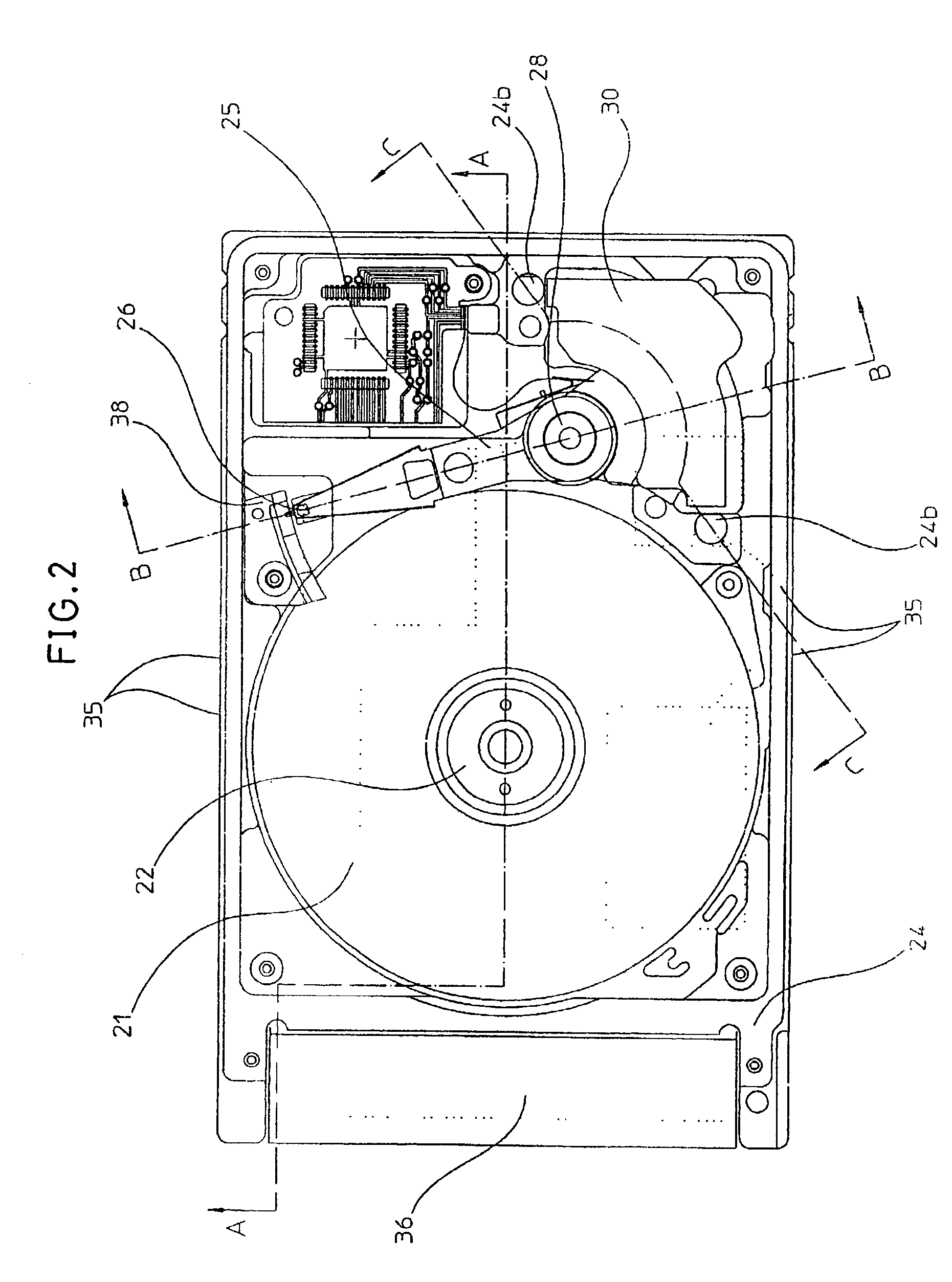
[0053] In the magnetic hard disk drive as shown in FIG. 1 through FIG. 7, a mechanism part where a movable part exists and an electric circuit part for controlling this mechanism part are provided. The mechanism part forms a shielded space and the electric circuit part is arranged outside the shielded space.

[0054] Referring to these drawings, 21 denotes a magnetic disk on and from which information is recorded and reproduced, and this magnetic disk 21 is attached to a spindle motor 23 by a clamp 22. The spindle motor 23 is attached to a frame body 24. 25 denotes an actuator on which a magnetic head 26 which carries out recording and reproduction of information and a coil 27 are mounted. The actuator 25 is provided with a ball bearing 28 and the actuator 25 is rotatably attached to the frame body 24 via this ball bearing 28. 29 denotes a perma...


PUM


Abstract

A disk device such as a magnetic hard disk drive. A disk is arranged inside a frame body. A cover is placed on the frame body, a gap is formed between a rim of the cover and the frame, and this gap is shielded by a sheet having an adhesive portion.

Description

[0001] The present invention relates to a disk device such as a magnetic hard disk drive and the like.[0002] Conventionally, as one type of hard magnetic disk devices, a magnetic hard disk drive which conforms to the Personal Computer Memory Card International Association (PCMCIA) "Type II standards" is known. This hard magnetic disk device comprises a mechanism part where a movable part exists and an electric circuit part for controlling this mechanism part. The mechanism part forms a shielded space and the electric circuit part is arranged outside this shielded space.[0003] In the mechanism part, an actuator as the movable part is provided inside a frame body. This actuator causes a magnetic head for recording and reproducing information to shift with respect to a magnetic disk on and from which information is recorded and reproduced. The frame body is covered by a top cover. This top cover has an adhesive portion on the peripheral portion thereof, is adhered to the frame body by ...

Claims


Application Information

Patent Timeline
IPC IPC(8): G11B33/02G11B21/02G11B25/04G11B33/12
CPCG11B25/043G11B33/121G11B5/4813G11B33/022G11B33/027G11B33/12G11B2220/2508
Inventor WATANABE, MASASHITAKASHIMA, TETSUYA
Owner PANASONIC HEALTHCARE HLDG CO LTD
Why Eureka
Try Eureka