Bird feeder assembly and method

a technology for bird feeders and parts, applied in the field of bird feeder assembly, can solve the problems of difficult maintenance of most bird feeders mounted on rigid posts, difficulty in replenishing without ladders or other special equipment, and difficulty in maintaining and maintaining bird feeders mounted at a safer height. , to achieve the effect of easy observation, abundant space, and convenient viewing

Inactive Publication Date: 2003-01-30
NICHOLAS TIMOTHY E
View PDF0 Cites 9 Cited by
  • Summary
  • Abstract
  • Description
  • Claims
  • Application Information

AI Technical Summary

Benefits of technology

0010] The aforesaid objectives and advantages are realized by a bird feeder assembly and method which allows the owner enjoyment while observing and convenience in maintenance. The bird feeder includes a mounting post consisting of an upper section and an anchor section to permit the feed containers thereon to be elevated approximately 3 meters from the ground. In the preferred form of the invention a winch is provided which is manually rotated to wind a cord affixed to a collar to raise and lower the same. The collar includes a plurality of arms from which multiple feed containers are suspended which can be readily observed as birds feed therefrom.
0011] While the main purpose of the device is for use in feeding wild birds, wind chimes, flower baskets or the like can also be supported from the arms as desired. Hoisting and lowering the feed containers, wind chimes or the like is easily accomplished by removing a locking pin in the winch whereby a handle can be rotated to raise or lower the collar as needed. Once the collar has been hoisted to the desired height along the mounting post, the locking pin is replaced which prevents rotation of the handle. The use of the extending arms provide abundant space for many birds to perch simultaneously, while other birds feed. The length of the arms provide separation of the feed containers, permitting various species of birds to be easily viewed at the same time at different food containers without obstruction to the line of sight.

Problems solved by technology

Most bird feeders which are mounted on a rigid post are difficult to maintain without a ladder unless they are positioned only a few feet from the ground.
However, bird feeders which are elevated only a few feet are subject to aggression by dogs, cats, squirrels and other predators whereas bird feeders mounted at a safer height are difficult to maintain and replenish without a ladder or other special equipment.

Method used


Image

  • Bird feeder assembly and method
  • Bird feeder assembly and method
  • Bird feeder assembly and method

Examples


Embodiment Construction

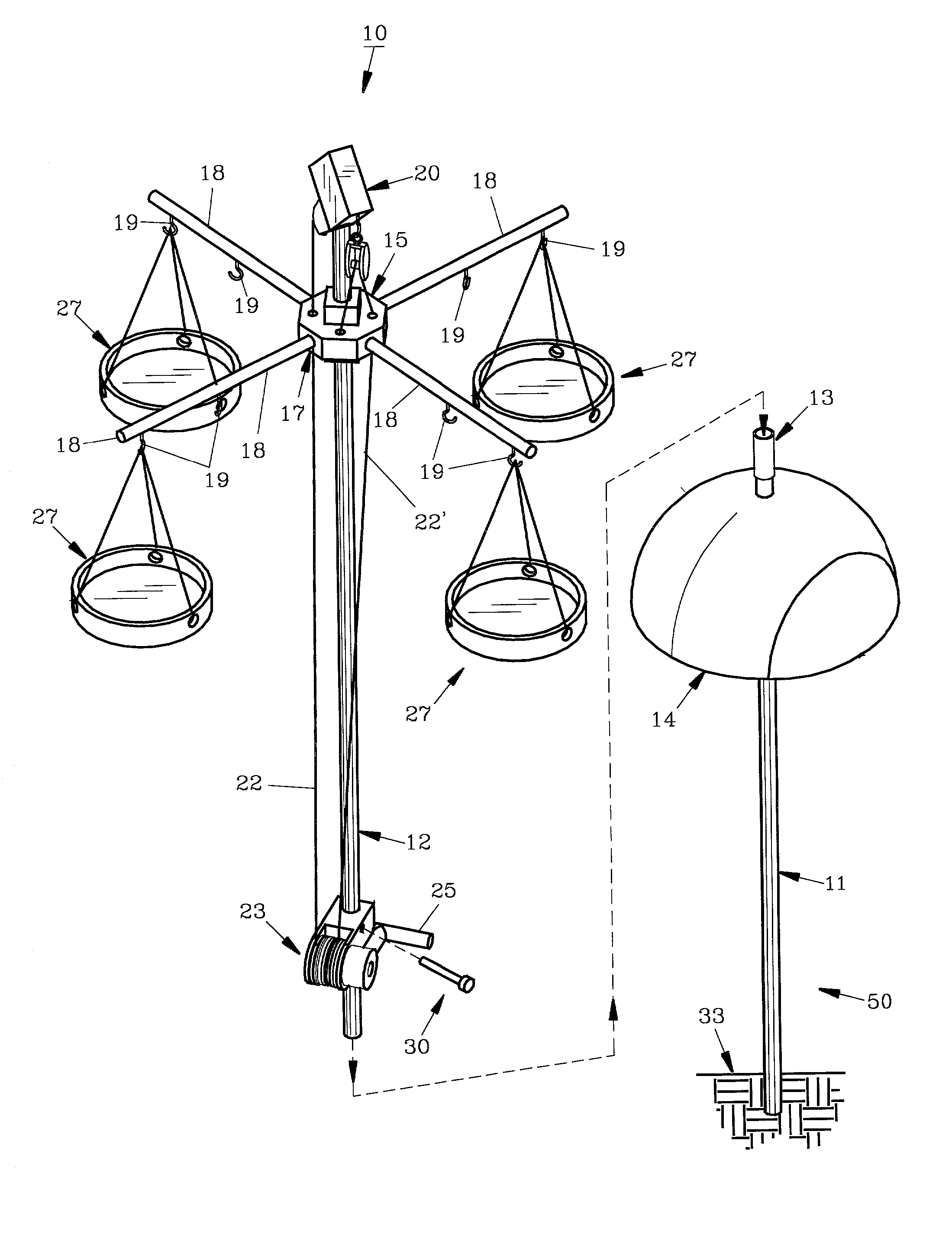
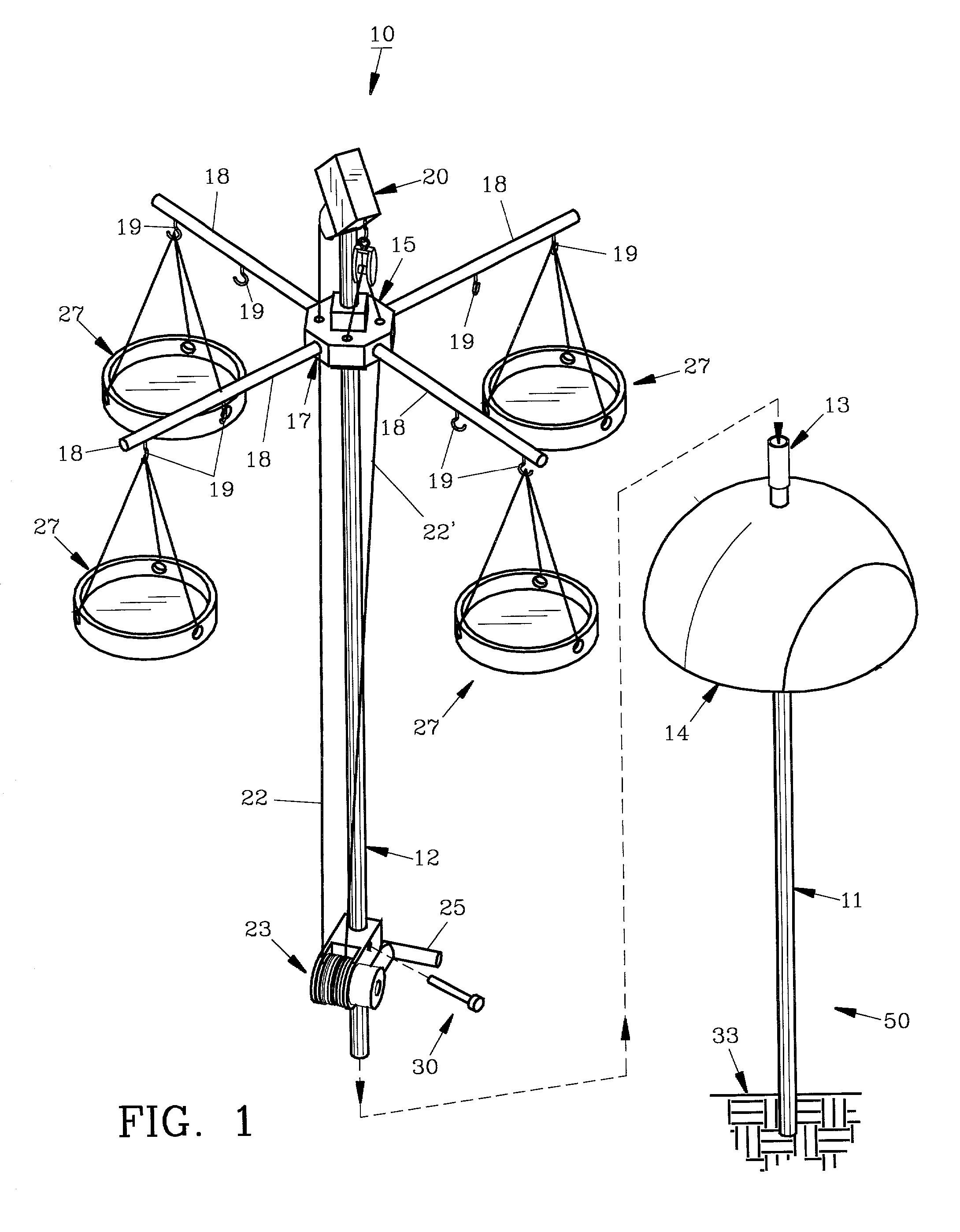
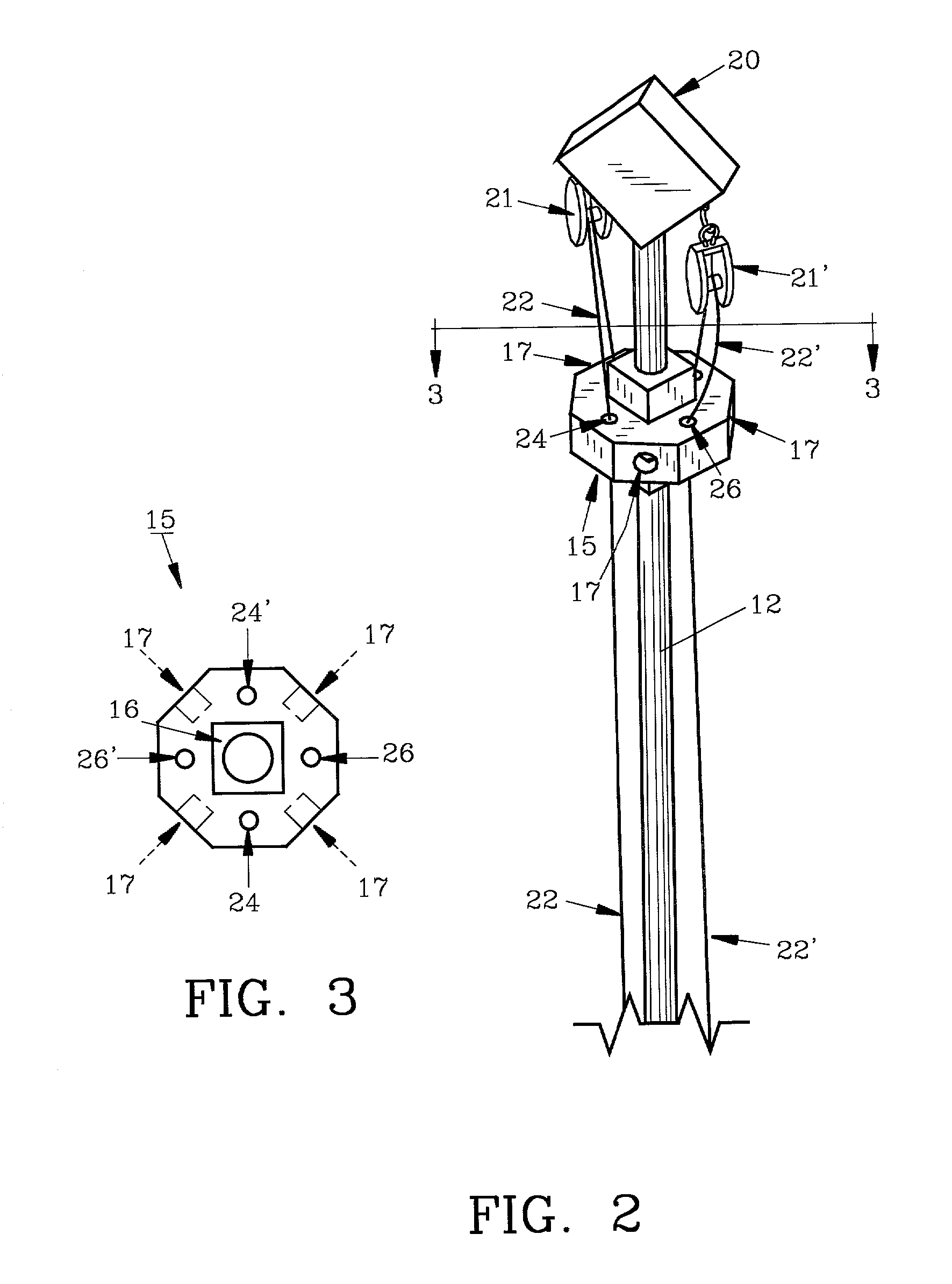
[0016] For a better understanding of the invention and its operation, turning now to the drawings, FIG. 1 illustrates preferred bird feeder assembly 10 with tubular mounting post 50 shown disassembled with anchor section 11 separated from upper section 12. Anchor section 11 is preferably formed of aluminum pipe and may have a diameter of approximately 3 / 4" (1.9 cm) and a length of 1.5 meters for placement in ground 33. Connector 13 is positioned atop anchor section 11 for receiving upper section 12, also preferably formed from aluminum pipe. Connector 13 could also be formed to internally join (not seen) anchor section 11 with upper section 12. A conventional squirrel guard 14 formed from plastic is affixed to anchor section 11 as an added security feature. Collar 15 is slidably positioned along upper section 12 which also has a length of preferably 1.5 m and is preferably formed from wood although it may be formed from aluminum or plastic. While anchor section 11 is seen in ground ...


PUM


Abstract

A bird feeder and method is provided having a collar slidably positioned on an upright mounting post. The collar includes sockets for extending arms therefrom to suspend bird feed containers, wind chimes, flower baskets or the like. The collar is connected to a cord and pulley arrangement whereby the feed containers can be raised and lowered as necessary for replenishment, cleaning and maintenance. In the preferred form of the invention a manual winch is attached to the post for ease in raising and lowering the feed containers.

Description

[0001] The invention herein pertains to bird feeders and particularly to a hoistable bird feeder having a multiplicity of feed containers.DESCRIPTION OF THE PRIOR ART AND OBJECTIVES OF THE INVENTION[0002] In recent years wild bird feeding stations and platforms have become increasingly popular for homeowners and others. Such bird feeders however need to be maintained with regularity to both replenish the feed supply and for cleaning purposes. Most bird feeders which are mounted on a rigid post are difficult to maintain without a ladder unless they are positioned only a few feet from the ground. However, bird feeders which are elevated only a few feet are subject to aggression by dogs, cats, squirrels and other predators whereas bird feeders mounted at a safer height are difficult to maintain and replenish without a ladder or other special equipment. Suspension systems have been developed for raising and lowering bird feeders mounted in trees as shown in U.S. Pat. No. 5,503,108. A bi...

Claims


Application Information

Patent Timeline
Patent Type & Authority Applications(United States)
IPC IPC(8): A01K39/014
CPCA01K39/014
Inventor NICHOLAS, TIMOTHY E.
Owner NICHOLAS TIMOTHY E
Why Eureka
Try Eureka