ISM band to U-NII band frequency transverter and method of frequency transversion

a frequency transverter and band technology, applied in the field of frequency translators, can solve the problems of increasing interference from a variety of devices, overcrowded 900 mhz and 2.4 ghz unlicensed frequencies, and increasing congestion of fixed wireless local area networks (lans),

Inactive Publication Date: 2003-01-30
HONEYWELL FED MFG & TECHNOLOGI
View PDF19 Cites 31 Cited by
  • Summary
  • Abstract
  • Description
  • Claims
  • Application Information

AI Technical Summary

Problems solved by technology

As a result, the 900 MHz and 2.4 GHz unlicensed frequencies are becoming increasingly overcrowded and congested.
Thus, fixed wireless local area networks (LANs), for example, involving digitally encoded data modulated onto an RF carrier signal in the 2.4 GHz ISM band, suffer increasing interference from a variety of devices, such as, for example, microwave ovens, cordless telephones, and Bluetooth apparatuses.
Unfortunately, the ISM band is insufficient to allow for wireless transmission of this information within and among these networks.
Unfortunately, prior art frequency translators suffer from a number of problems and disadvantages, including, for example, that they are typically only two-terminal devices and require a different antenna for each frequency band.
Furthermore, though the FCC precludes transmission at both frequency bands simultaneously, no provision is made to maintain a connection at the originating frequency.
Additionally, up/down translation in prior art frequency translators between the first and second frequency bands can result in a phase noise which is undesirably higher than that of the signal's source, and can result in substantial undesirable spurious products.
Additionally, it is well known that multipath levels cause increasing signal deterioration with increasing data rate, particular...

Method used


Image

  • ISM band to U-NII band frequency transverter and method of frequency transversion
  • ISM band to U-NII band frequency transverter and method of frequency transversion
  • ISM band to U-NII band frequency transverter and method of frequency transversion

Examples


Embodiment Construction

, below.

[0023] A preferred embodiment of the present invention is described in detail below with reference to the attached drawing figures, wherein:

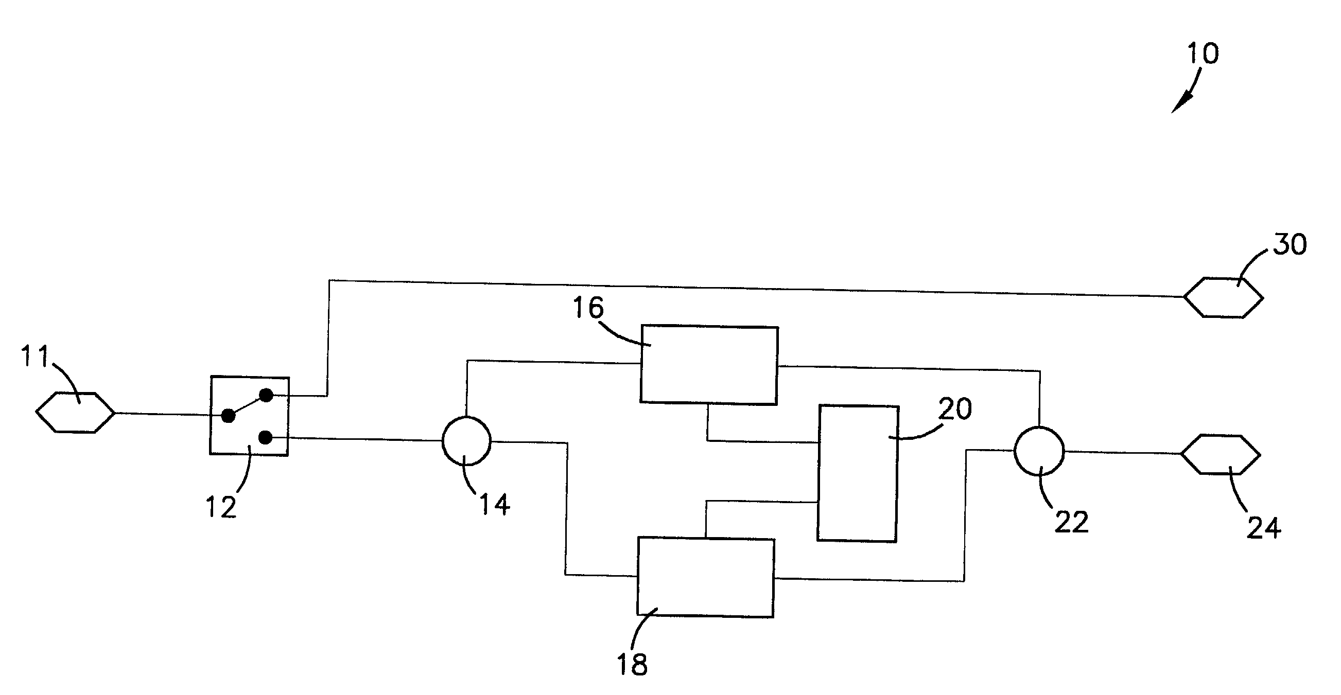
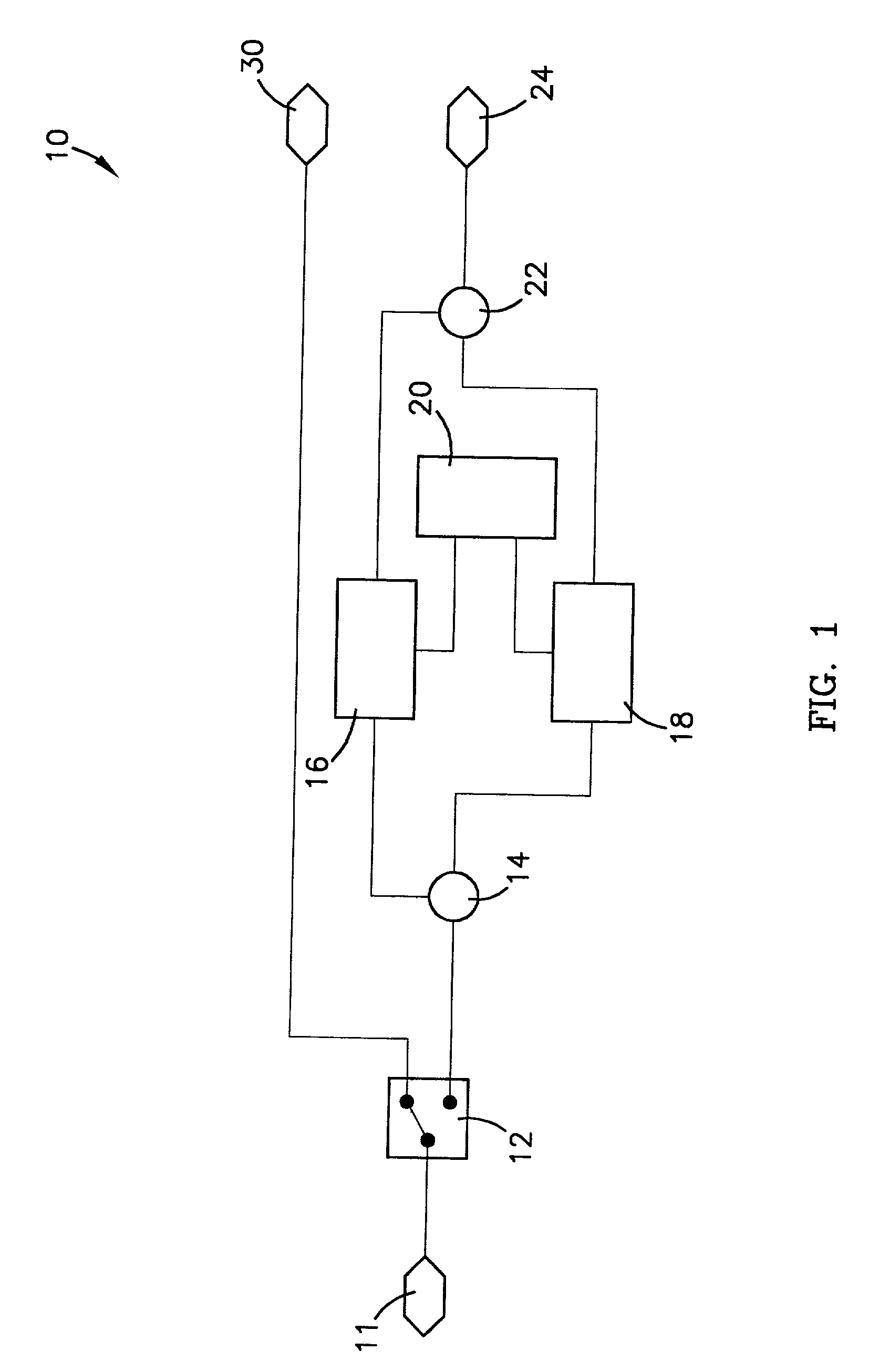
[0024] FIG. 1 is a block diagram of a preferred embodiment of the frequency transverter of the present invention;

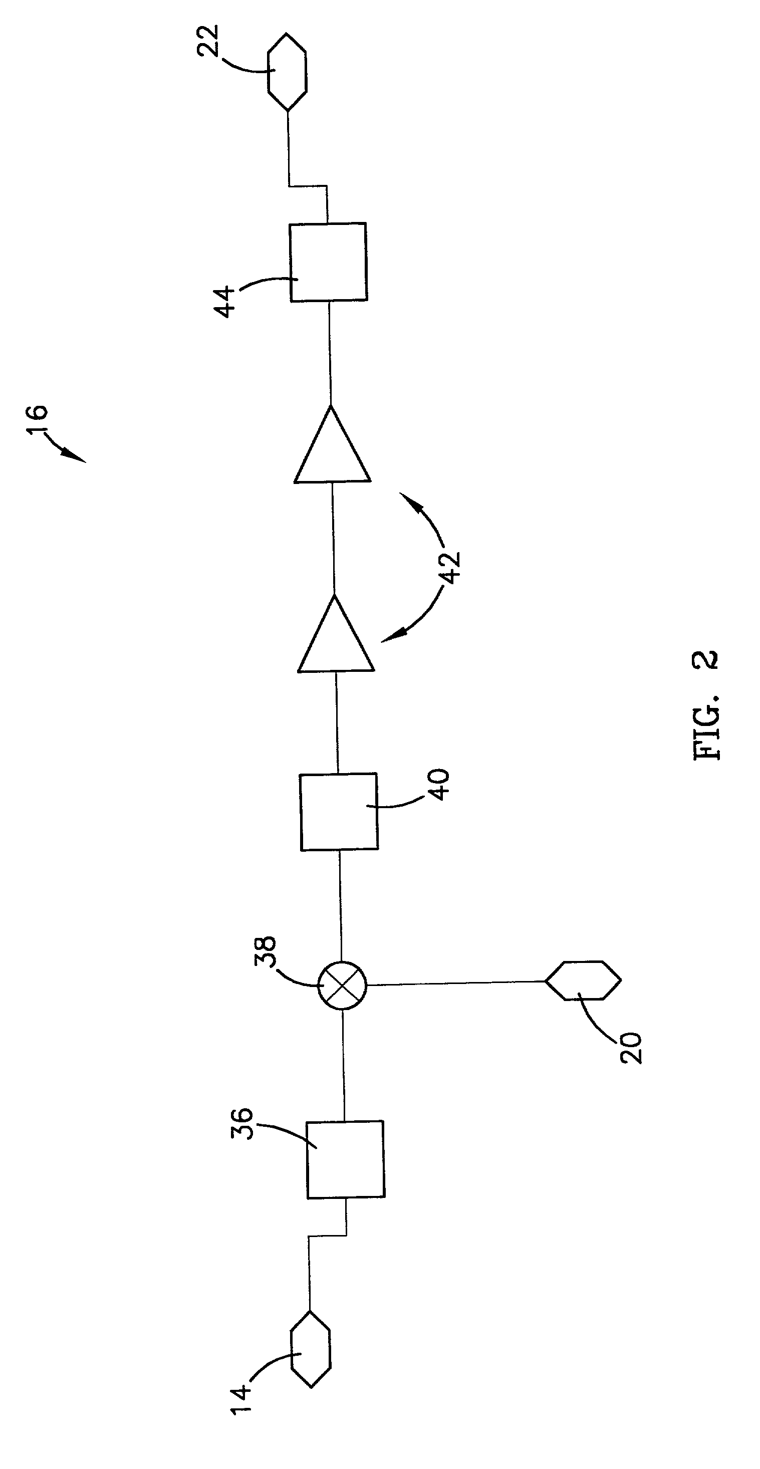
[0025] FIG. 2 is a block diagram of a transmuter component of the frequency transverter of FIG. 1;

[0026] FIG. 3 is a block diagram of a converter component of the frequency transverter of FIG. 1;

[0027] FIG. 4 is a block diagram of a multiplier portion of a local oscillator component of the frequency transverter of FIG. 1;

[0028] FIG. 5 is a block diagram of a fundamental phase-locked-loop portion of the local oscillator component;

[0029] FIG. 6 is a diagram of a wireless communications link setup utilizing the frequency transverter of FIG. 1; and

[0030] FIG. 7 is a block diagram of a fixed communications link setup utilizing the frequency transverter of FIG. 1.

DETAILED DESCRIPTION OF A PREFERRED EMBODIMENT

[0031] Referring to the ...


PUM


Abstract

A frequency transverter (10) and method for enabling bi-frequency dual-directional transfer of digitally encoded data on an RF carrier by translating between a crowded or otherwise undesirable first frequency band, such as the 2.4 GHz ISM band, and a less-crowded or otherwise desirable second frequency band, such as the 5.0 GHz-6.0 GHz U-NII band. In a preferred embodiment, the transverter (10) connects between an existing data radio (11) and its existing antenna (30), and comprises a bandswitch (12); an input RF isolating device (14); a transmuter (16); a converter (18); a dual output local oscillator (20); an output RF isolating device (22); and an antenna (24) tuned to the second frequency band. The bandswitch (12) allows for bypassing the transverter (10), thereby facilitating its use with legacy systems. The transmuter (14) and converter (16) are adapted to convert to and from, respectively, the second frequency band.

Description

[0001] The present application is related to and claims priority benefit of the filing date of a provisional application titled "ISMUNII Transverter", Serial No. 60 / 298,218, filed Jun. 14, 2001, which is hereby incorporated by reference into the present application.[0003] 1. Field of the Invention[0004] The present invention relates broadly to frequency translators and methods for translating a radio frequency (RF) signal between a first frequency band and a second frequency band. More particularly, the present invention concerns a frequency transverter and method for enabling bi-frequency dual-directional transfer of digitally encoded data on an RF carrier by translating between a first frequency band, such as the 2.4 GHz ISM band, and a second frequency band, such as the 5.0 GHz-6.0 GHz U-NII band.[0005] 2. Description of the Prior Art[0006] Developments in a number of different digital technologies have greatly increased the need to transfer large amounts of data from one network...

Claims


Application Information

Patent Timeline
IPC IPC(8): H04B1/00H04B1/26H04B1/40
CPCH04B1/00H04B1/005H04B1/0096H04B1/406
Inventor STEPP, JEFFREY DAVIDHENSLEY, DALE
Owner HONEYWELL FED MFG & TECHNOLOGI
Why Eureka
Try Eureka