Optical switching apparatus with adiabatic coupling to optical fiber

a technology of optical fiber and optical switching device, which is applied in the direction of optics, optical waveguide light guide, instruments, etc., can solve the problems of high data transmission rate imposing strong requirements on the functionality of switching device, existing optical switching device which employs signal conversion from optical into electrical and back into optical does not meet those requirements, and the integration process of such type of switching device is not robust, reliable, and extendabl

Inactive Publication Date: 2003-02-20
FUJITSU LTD
View PDF53 Cites 47 Cited by
  • Summary
  • Abstract
  • Description
  • Claims
  • Application Information

AI Technical Summary

Problems solved by technology

Furthermore, high data transmission rates impose strong requirements on the functionality of the switching devices.
Existing optical switching devices which employ signal conversion from optical into electrical and back into optical do not satisfy those requirements.
Although, the main principle of the optical cross connect switching based on the light beam deflection is well known, a robust, reliable, low cost and extendable integration process for such type of switching device is not available.
However, these optical switching

Method used


Image

  • Optical switching apparatus with adiabatic coupling to optical fiber
  • Optical switching apparatus with adiabatic coupling to optical fiber
  • Optical switching apparatus with adiabatic coupling to optical fiber

Examples


Embodiment Construction

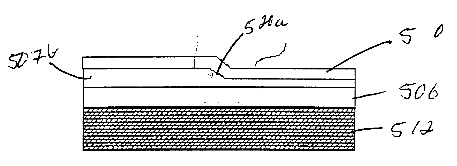
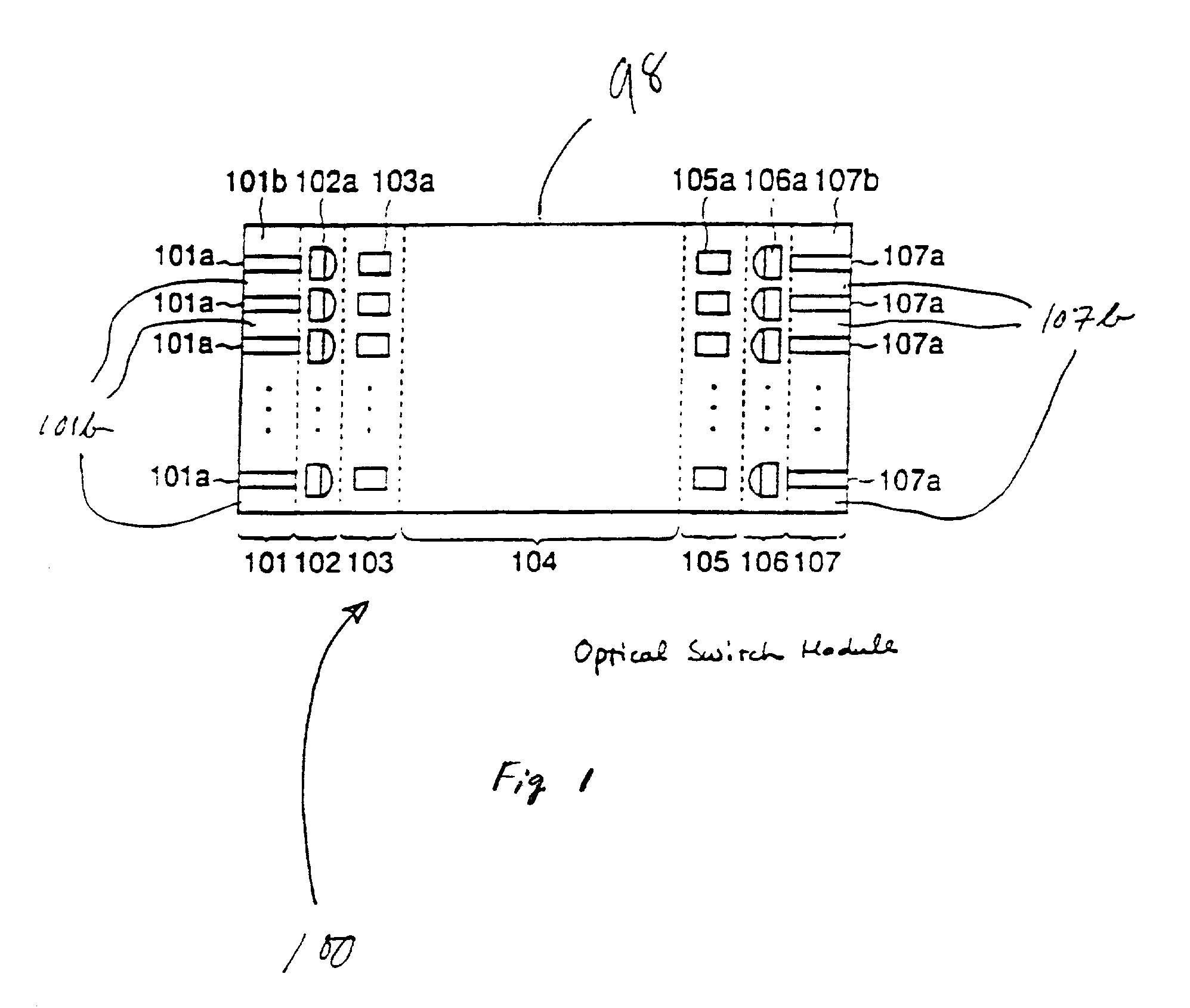
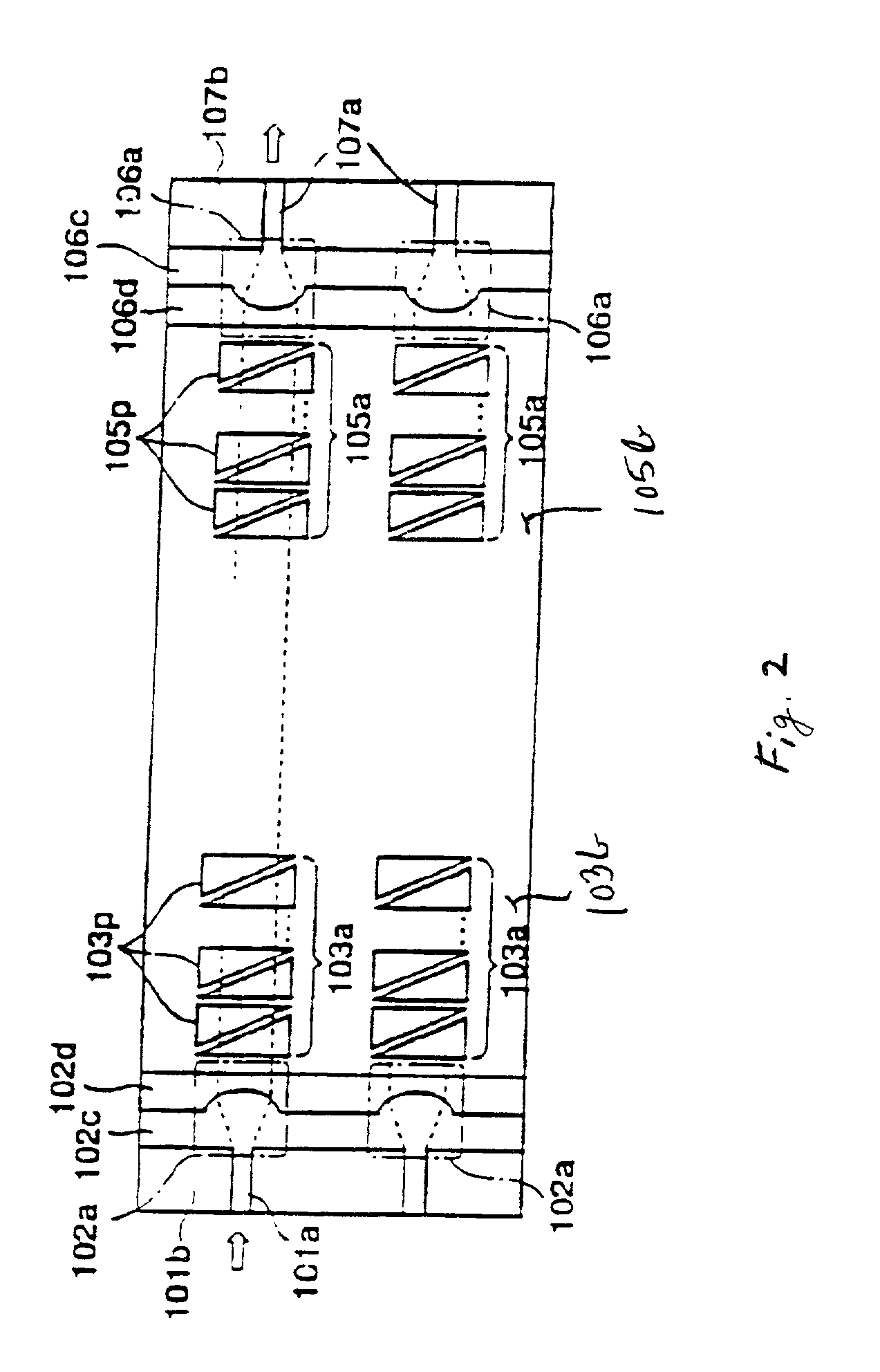
[0034] Referring in detail now to the drawings in combination with the detailed description hereinafter presented, there is illustrated and described an integration process, which allows fabrication of a non-blocking optical cross connect switching matrix with a large (e.g., at least up to 4000) number of I / O channels. The functional principle of the device is based on the EO induced deflection of the incoming optical beam or optical signal that can reroute the incoming light signal from an input port to an output port. Physical principle of the EO induced light beam deflection in piezoelectric materials is well known and is described in an article entitled "Low-Voltage Drive Electro-Optic Pb (Zr, Ti) O.sub.3 Waveguide Devices Fabricated By Solid-Phase Epitaxy" to Nashimoto et al of the Corporate Research Laboratories of Fuji Xerox Co., Ltd., Japan.

[0035] The detailed description provides a hybrid integration process including an OE deflecting element disposed on a silicon substrate...


PUM


Abstract

A coupling structure is disclosed. An optical device includes a core layer for guiding a light beam exiting a core layer of an optical fiber. The core layer of the optical device avoids a power loss of a light beam and establishes an adiabatic coupling. The core layer of the optical device may have a tapered surface.

Description

[0001] This is a continuation-in-part application of copending application having application Ser. No. 09 / 932,526, filed Aug. 17, 2001. Benefit of the earlier filing date is claimed with respect to all common subject matter.[0002] 1. Field of the Invention[0003] This invention is related to an optical switching apparatus used in an optical network for voice and data communications. More particularly, embodiments of the present invention provide for an optical switching device with adiabatic coupling to an optical fiber and method for fabricating an optical switching device with an adiabatic coupling structure.[0004] 2. Description of the Related Art[0005] Strong growth of optical networks for voice and data communication results in huge demand for high data rate information transfer capabilities. To enable such transfer capabilities, dense wavelength division multiplexing (DWDM) technology has been developed which allows transfer of multiple wavelength over the same fiber leading to...

Claims


Application Information

Patent Timeline
IPC IPC(8): G02B6/13G02F1/31G02F1/313G02B6/12
CPCG02F1/31
Inventor GLEBOV, ALEXEISASAKI, SHINYALEE, MICHAEL
Owner FUJITSU LTD
Why Eureka
Try Eureka