Fuel injection device of cylinder injection type internal combustion engine and fuel injection method thereof

a fuel injection device and internal combustion engine technology, which is applied in the direction of engine starters, electric control, machines/engines, etc., can solve the problems of deteriorating fuel efficiency, small quantity of fuel injection according to requirements, and deteriorating start performan

Inactive Publication Date: 2003-03-06
TOYOTA JIDOSHA KK
View PDF6 Cites 33 Cited by
  • Summary
  • Abstract
  • Description
  • Claims
  • Application Information

AI Technical Summary

Problems solved by technology

On the other hand, the auxiliary fuel injection valve introduces the low-pressure fuel supplied from the feed pump, and injects the low-pressure fuel into the intake channel since pressurizing the fuel is unnecessary.
However, in the fuel injection device above, vapor may be generated in a high-pressure fuel pipe supplying the high-pressure fuel to the main fuel injection valve when the engine is started after high-temperature soaking.
The vapor delays the pressurization of the fuel when the engine is started, so that the atomization of the fuel becomes i

Method used


Image

  • Fuel injection device of cylinder injection type internal combustion engine and fuel injection method thereof
  • Fuel injection device of cylinder injection type internal combustion engine and fuel injection method thereof
  • Fuel injection device of cylinder injection type internal combustion engine and fuel injection method thereof

Examples


Embodiment Construction

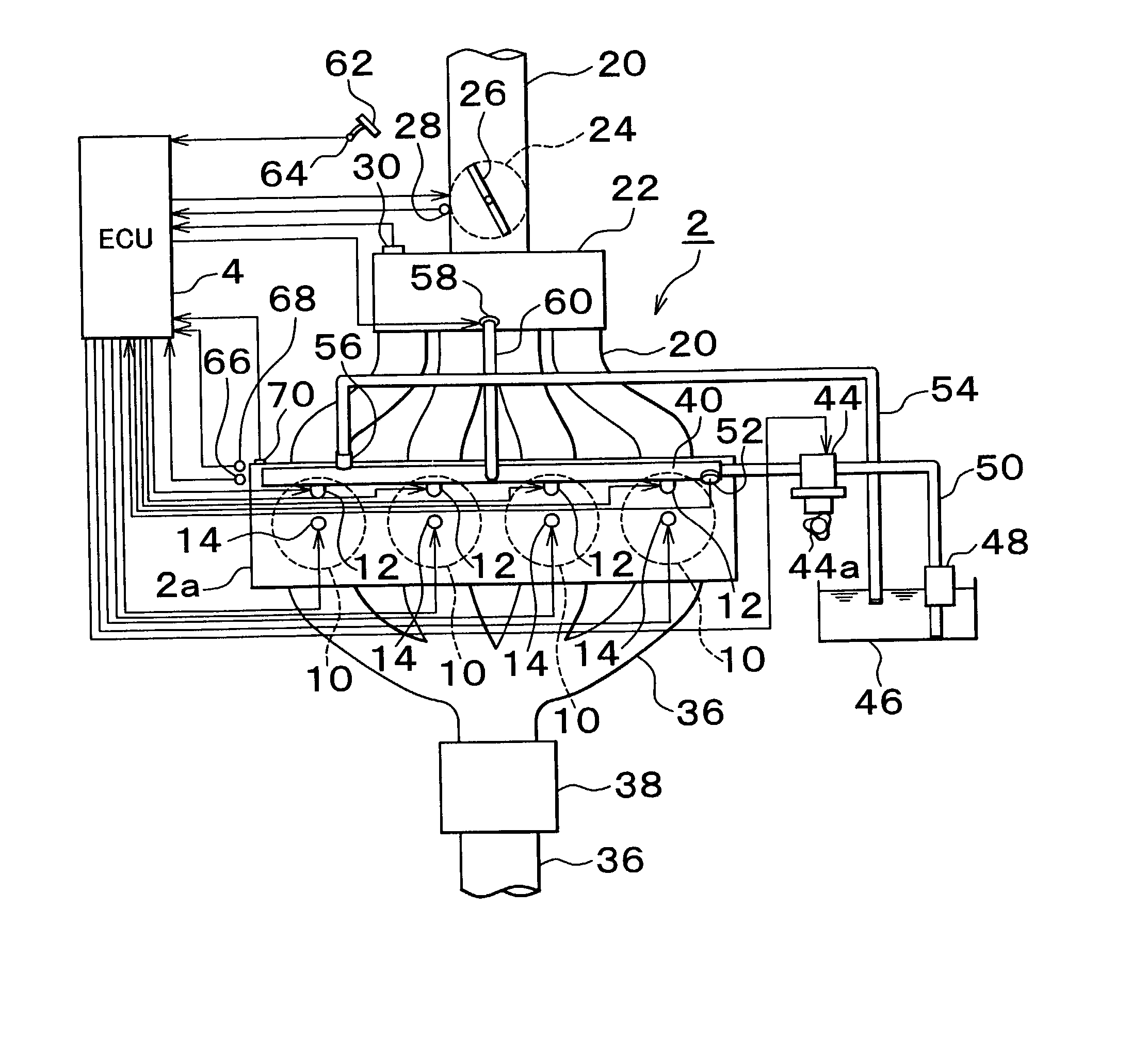
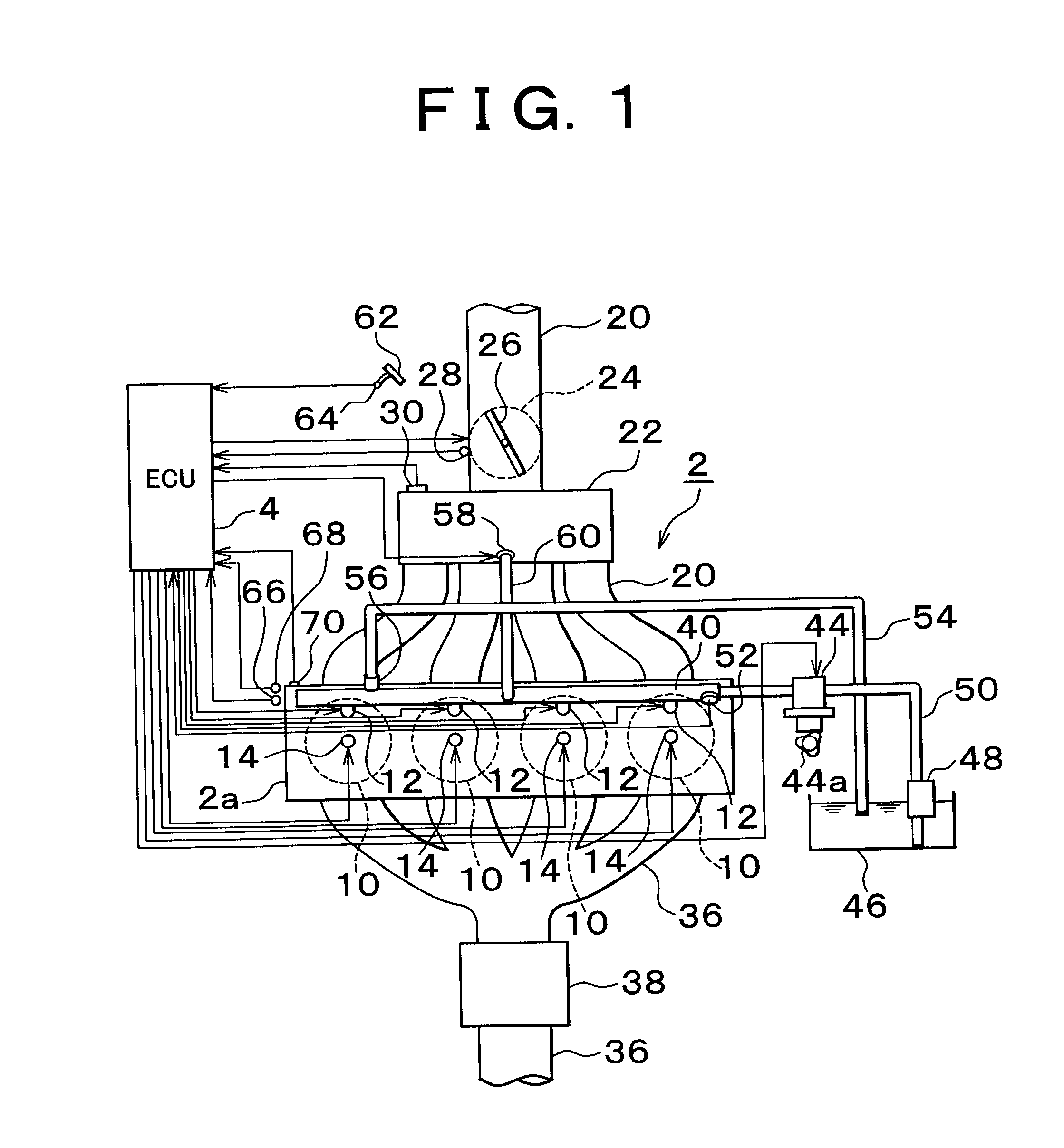
[0030] FIG. 1 shows a schematic configuration of a cylinder injection type gasoline engine 2 (hereinafter engine 2) mounted on a vehicle and its electronic control unit 4 (controller) (hereinafter ECU 4). Output of the engine 2 is transmitted to wheels (not shown) of a vehicle as a driving force that travels through a transmission (not shown). Main fuel injection valves 12 for directly injecting a fuel and ignition plugs 14 for igniting the injected fuel are provided in combustion chambers 10 of the engine 2. Intake ports (not shown), connected to the combustion chambers 10, are opened and closed by the movement of intake valves (not shown). A surge tank 22 is provided at a point midway of an intake channel 20 connected to the intake ports. A throttle valve 26, whose opening is adjusted by a throttle motor 24, is provided upstream of the surge tank 22. An intake quantity is adjusted by the opening (throttle opening TA) of the throttle valve 26. The throttle opening TA is detected by...


PUM


Abstract

A fuel injection device and method includes a main injection valve that injects a high-pressure fuel supplied to a delivery pipe into each combustion chamber of an engine, and an auxiliary fuel injection valve supplied with the high-pressure fuel from the delivery pipe. The auxiliary fuel injection valve is capable of injecting the high-pressure fuel in sucked air flowing in a surge tank when the engine is started under cold conditions. In addition, a fuel pressure can rapidly be increased in a starting phase since vapor in the delivery pipe can be discharged by temporarily opening the auxiliary fuel injection valve.

Description

INCORPORATION BY REFERENCE[0001] The disclosure of Japanese Patent Application No. 2001-263494 filed on Aug. 31, 2001, including the specification, drawing, and abstract is incorporated herein by reference in its entirety.[0002] 1. Field of Invention[0003] The present invention relates to a fuel injection device of a cylinder injection type internal combustion engine, which includes a main fuel injection valve for injecting a fuel into each combustion chamber of the engine with multiple cylinders, and being supplied with a high-pressure fuel from a high-pressure fuel channel, and to a fuel injection method thereof.[0004] 2. Description of Related Art[0005] As for a spark ignition internal combustion engine for injecting a fuel into a combustion chamber or a so-called cylinder injection type internal combustion engine, an internal combustion engine, which includes an auxiliary fuel injection valve for injecting a fuel into an intake channel in addition to a main fuel injection valve ...

Claims


Application Information

Patent Timeline
IPC IPC(8): F02M63/00F02B17/00F02B23/08F02B23/10F02B75/12F02D41/02F02D41/06F02D41/12F02D41/38F02M55/02F02M69/00F02N99/00
CPCF02B17/005F02B23/08F02B23/10F02B2075/125F02D41/064F02D41/3094F02D41/3836F02D2041/389F02D2250/02F02N99/006F02N99/008Y02T10/123Y02T10/12
Inventor TSUCHIYA, TOMIHISA
Owner TOYOTA JIDOSHA KK
Why Eureka
Try Eureka