

Resin intake manifold
a technology of intake manifold and resin, which is applied in the direction of combustion-air/fuel-air treatment, air cleaners for fuel, charge feed systems, etc., can solve the problems of difficult mold design, difficult mold arrangement, freezing and blocking, etc., and achieves the effect of relatively easy manufacturing
- Summary
- Abstract
- Description
- Claims
- Application Information
AI Technical Summary
Benefits of technology
Problems solved by technology
Method used
Image

Examples
Embodiment Construction
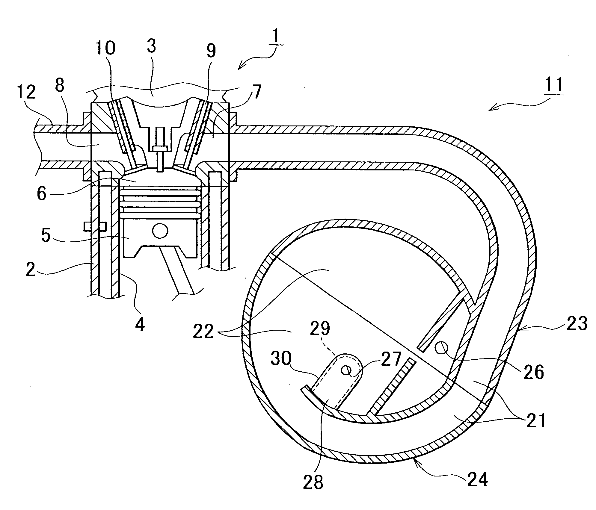
[0031] One example embodiment of the invention will hereinafter be described with reference to FIGS. 1 to 6. In this example embodiment, the internal combustion engine with which the intake manifold is used is a 4-cylinder gasoline engine to be mounted in a vehicle, for example. However, the engine is not limited to this. For example, it may have a different number of cylinders, or may be a diesel engine.
[0032] First, the arrangement of the intake manifold will briefly be described with reference to FIG. 1. In the drawing, an engine 1 is provided with a cylinder block 2 and a cylinder head 3.
[0033] The cylinder block 2 has a plurality of (in this case, four) cylinders 4, each of which has a piston 5 inserted therein which can move reciprocally. A combustion chamber 6 is formed in each cylinder 4 by the space between the upper end of the piston 5 and the cylinder head 3.
[0034] In the cylinder head 3, an intake port 7 and an exhaust port 8 are provided for each combustion chamber 6...
PUM
 Abstract
Description
Claims
Application Information