
Diagnostic for visual detection of media advance errors

a technology of error detection and imaging, applied in the field of imaging printers, can solve problems such as systemic nozzle contribution, and achieve the effects of increasing the number of media advances, increasing the effect of accumulated errors, and increasing the apparent visual

Inactive Publication Date: 2003-03-13
HEWLETT PACKARD DEV CO LP
View PDF4 Cites 5 Cited by
  • Summary
  • Abstract
  • Description
  • Claims
  • Application Information

AI Technical Summary

Benefits of technology

[0008] This disclosure is directed to a diagnostic technique that allows an easy visual detection of poor media advance calibration, which can be utilized by users (implemented in the trouble-shooting process of printers) and in printer development.
[0010] An aspect is to increase the number of media advances between the printing of sets of pixels, e.g. pixels in a horizontal line, thereby increasing the effect of accumulated errors and the apparent visual effect.

Problems solved by technology

The diagnostic technique employs a print mode that prints different areas of the plot at different passes with a controlled amount of advances between them; the dot positioning error in the different areas has a non-systematic nozzle contribution, that tends to cancel out, and a systematic contribution due to the accumulative media advance error.

Method used


Image

  • Diagnostic for visual detection of media advance errors
  • Diagnostic for visual detection of media advance errors
  • Diagnostic for visual detection of media advance errors

Examples


Embodiment Construction

[0024] Exemplary embodiments of this invention will be described with respect to large format printers, although the invention can also be practiced on other types of printers.

[0025] Commonly assigned U.S. Pat. No. 5,835,108, entitled CALIBRATION TECHNIQUE FOR MISDIRECTED INKJET PRINTHEAD NOZZLES, describes an exemplary large format color inkjet printer / plotter which can employ the recent invention. FIGS. 1-8 and the following description of these figures are generally taken from this patent, the entire contents of which are incorporated herein by this reference.

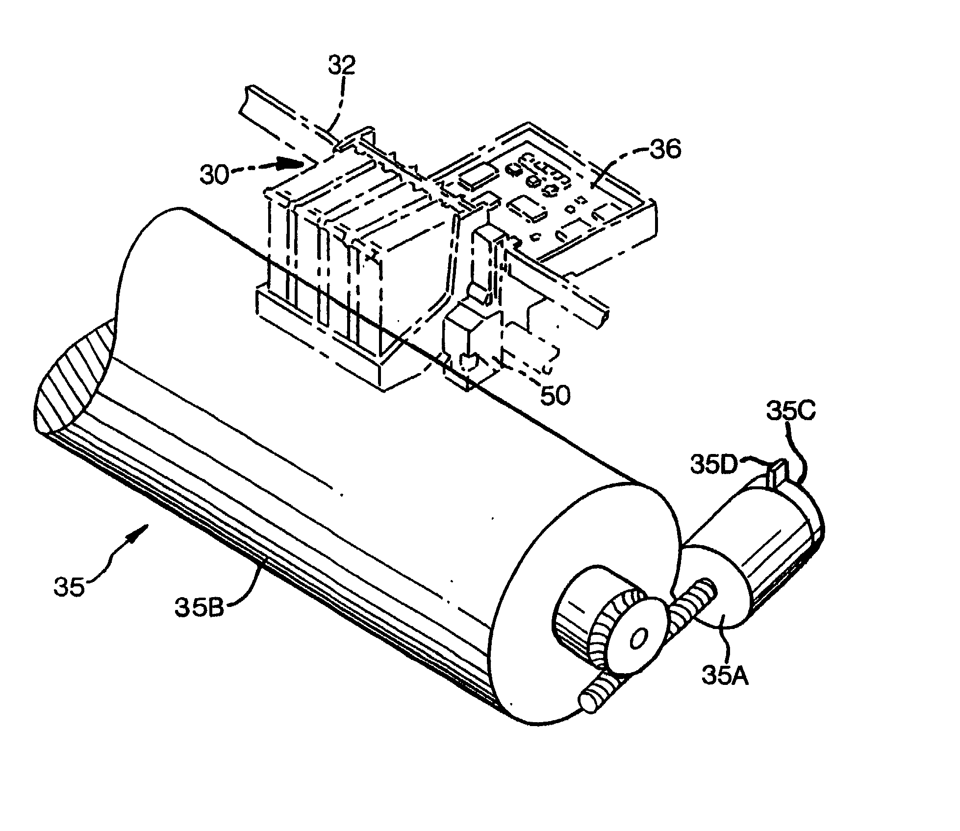
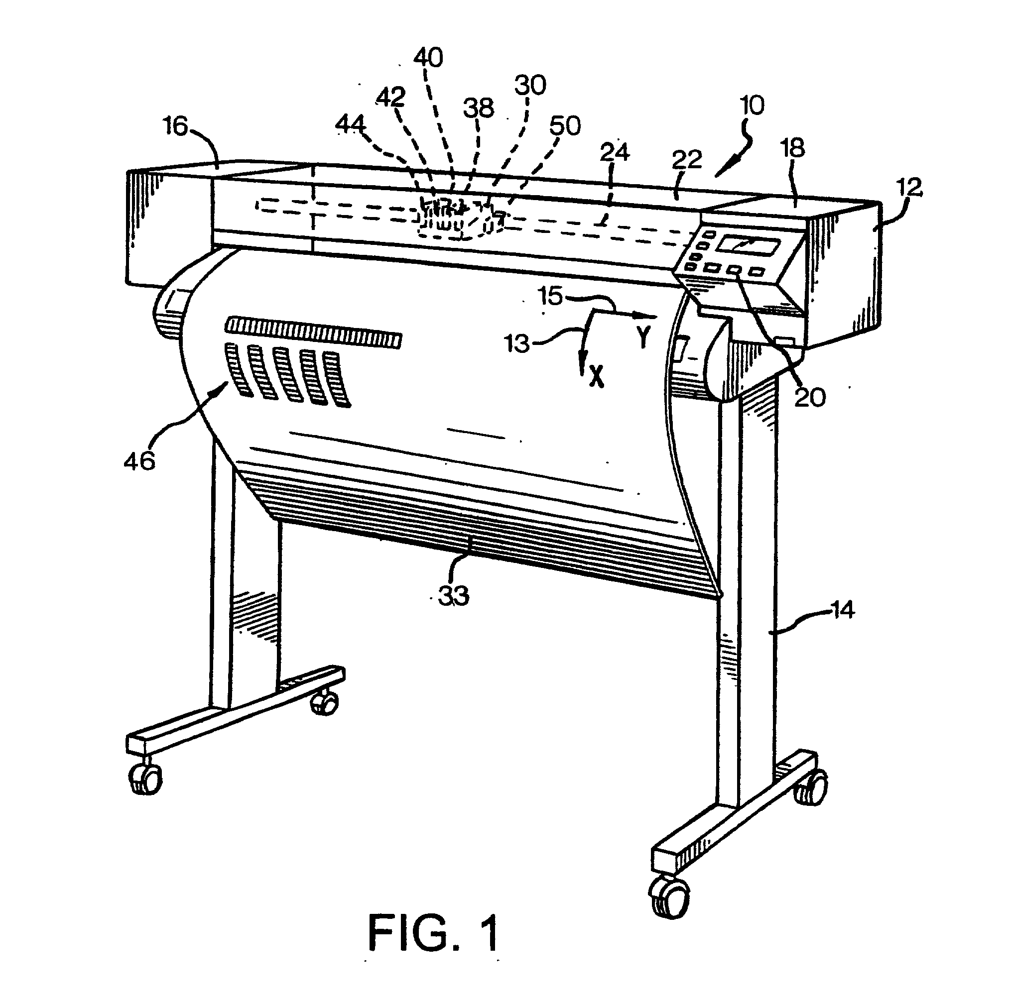
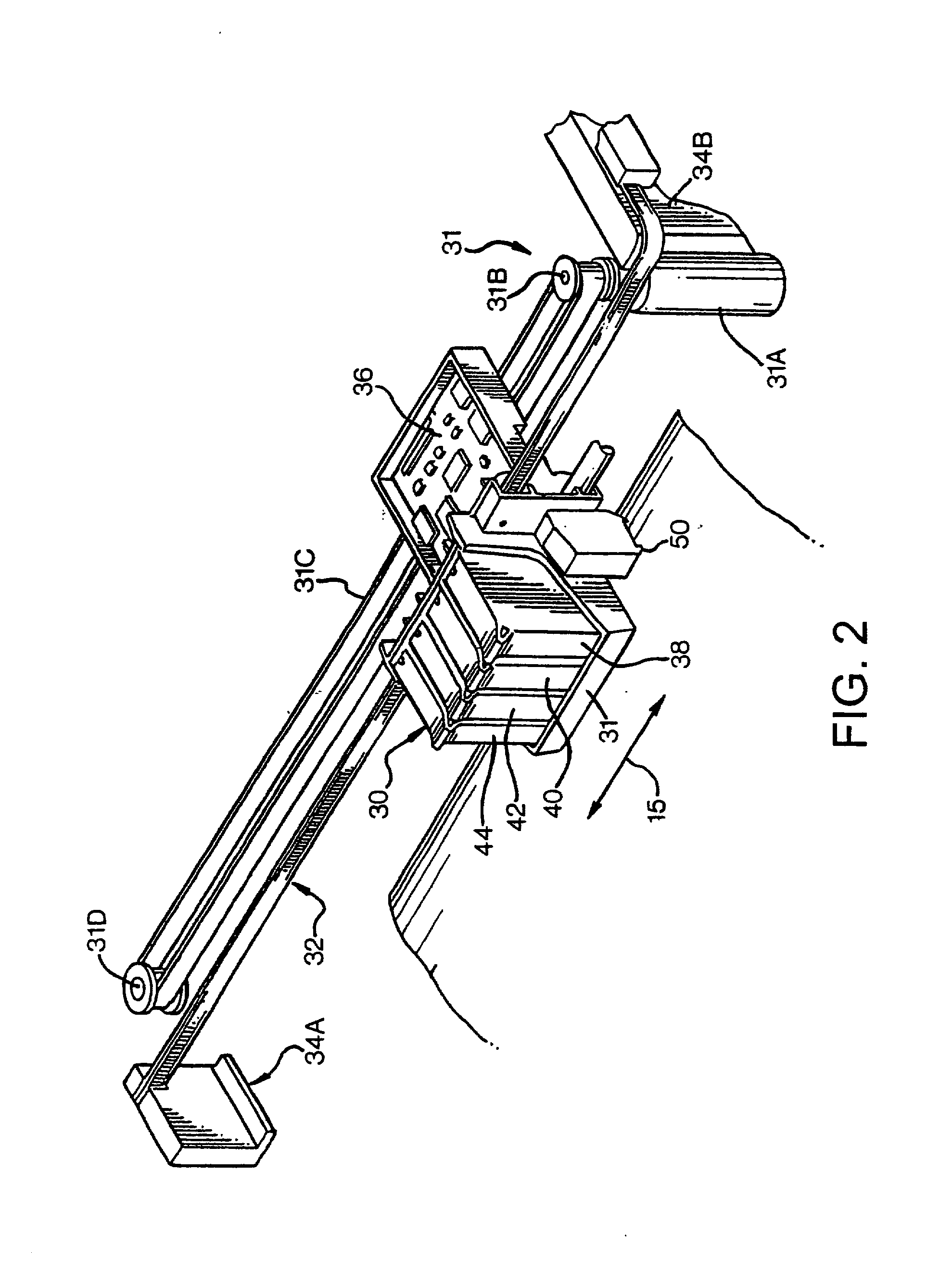
[0026] FIG. 1 is a perspective view of an inkjet printer / plotter 10 having a housing 12 mounted on a stand 14. The housing has left and right drive mechanism enclosures 16 and 18. A control panel 20 is mounted on the right enclosure 18. A carriage assembly 30, illustrated in phantom under a cover 22, is adapted for reciprocal motion along a carriage bar 24, also shown in phantom. The position of the carriage assembly 30 in a...


PUM


Abstract

A diagnostic technique allows an easy visual detection of poor media advance calibration. The diagnostic technique employs a print mode that prints different areas of the plot at different passes with a controlled amount of advances between them. The dot positioning error in the different areas has a non-systematic nozzle contribution, that tends to cancel out, and a systematic contribution due to the accumulative media advance error. Different patterns can be used to make the dot positioning error due to the accumulative media advance error show up. By increasing the number of media advances between the printing of sets of pixels, e.g. pixels in a horizontal line, the effect of accumulated errors and the apparent visual effect is increased.

Description

TECHNICAL FIELD OF THE DISCLOSURE[0001] This invention relates to inkjet printers, and more particularly to techniques for detecting media advance errors.BACKGROUND OF THE DISCLOSURE[0002] Large scale plotters typically support roll-form print media, i.e., a supply of paper or transparent film on a roll. The media is loaded into the printer, and is advanced along a media path to a print area. A swath-type printer includes a carriage mounted for scanning movement along a swath axis, transverse to the media path at the print area. Hereafter, the media path is known as the X-axis, and the scanning or swath axis is the Y-axis. For color printing, the carriage holds a plurality of ink-jet printheads, each for printing a different color ink, typically black, cyan, magenta and yellow. The printer includes a media drive mechanism for moving the media along the media path, and a carriage drive mechanism for scanning the carriage along the scan axis. The printer controller issues print contro...

Claims


Application Information

Patent Timeline
Patent Type & Authority Applications(United States)
IPC IPC(8): B41J29/393
CPCB41J2/2132
Inventor GARCIA, JOAN MANUELSUBIRADA, FRANCESC
Owner HEWLETT PACKARD DEV CO LP
Learn More