Vehicle steering control system

a steering control and vehicle technology, applied in the direction of steering initiation, instruments, vessel construction, etc., can solve the problems of reducing the rigidity of the second steering unit, unable to satisfy the calculation of difficulty in derive or calculate the steering reaction force, etc., to achieve accurate information on the roughness degree of the road surface

Inactive Publication Date: 2003-03-20
NISSAN MOTOR CO LTD
View PDF6 Cites 34 Cited by
  • Summary
  • Abstract
  • Description
  • Claims
  • Application Information

AI Technical Summary

Benefits of technology

0009] It is therefore an object of the present invention to provide a vehicle steering control system which, without the aid of an additional sensor, can provide an accurate information on a roughness degree of road surface even when the roughness degree is small to such a degree as not induce a marked behavior of the associated motor vehicle.

Problems solved by technology

However, regarding information on a roughness degree of road surface, it is very difficult to derive or calculate the steering reaction force because the behavior of the motor vehicle caused by such roughness of road surface is quite small.
The arrangement of the torque sensor proposed by this publication however tends to reduce the rigidity of the second steering unit because of the nature of the actually employed torque sensor.
However, even in this measure, satisfied calculation of the steering reaction force has not been carried out because of contradiction of usage of such "linear" equation in the field of steering system which has "nonlinear" characteristics.

Method used


Image

  • Vehicle steering control system
  • Vehicle steering control system
  • Vehicle steering control system

Examples


Embodiment Construction

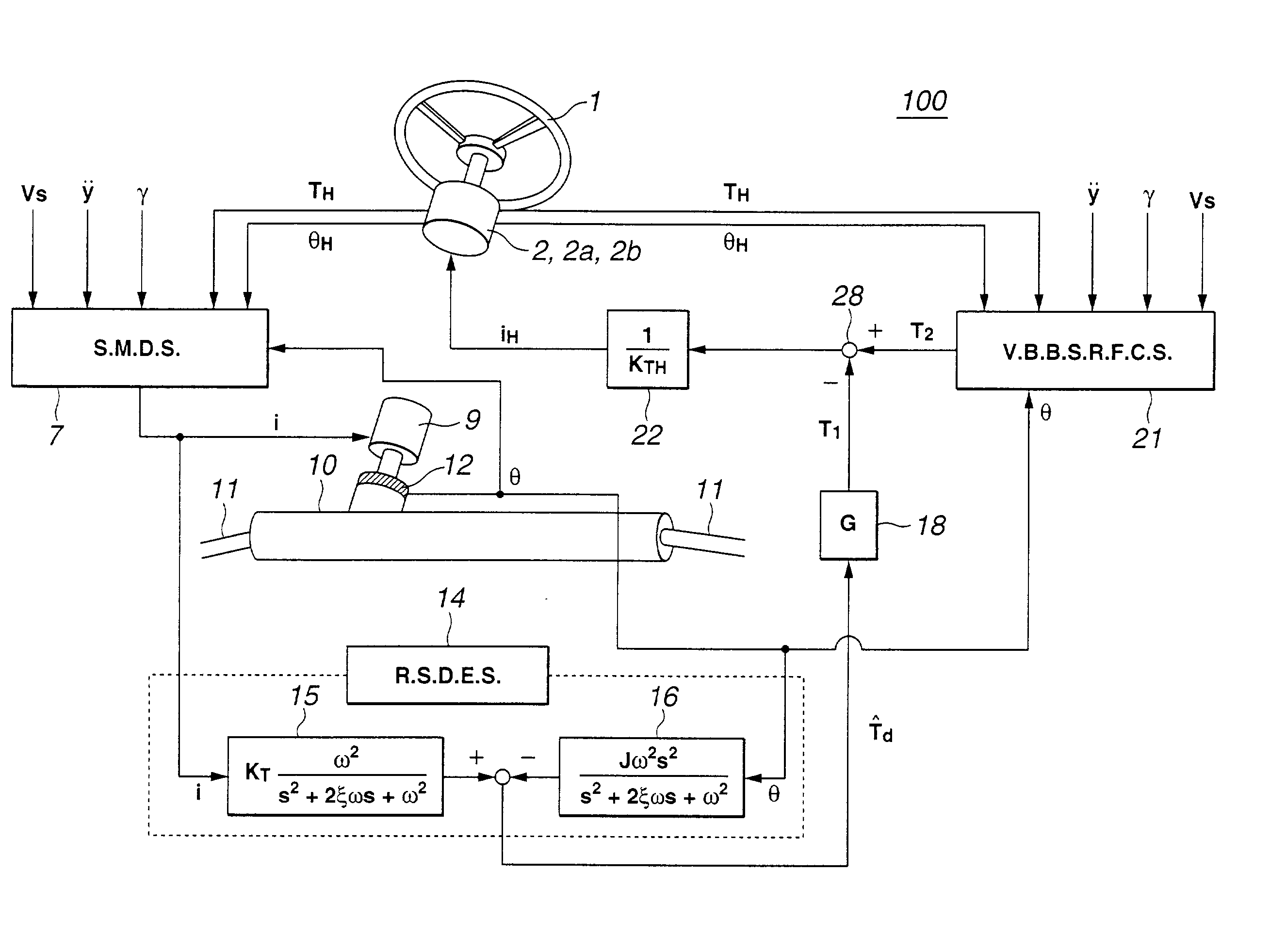
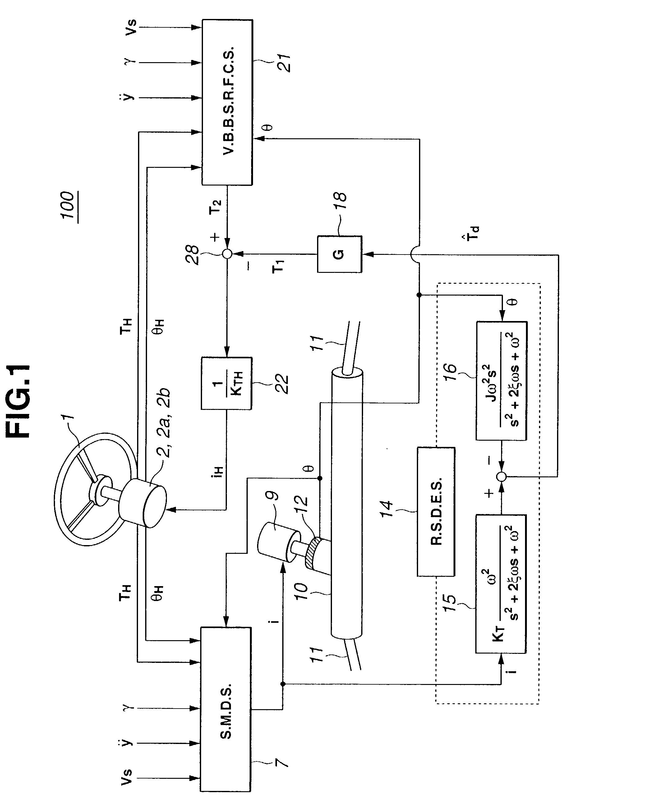
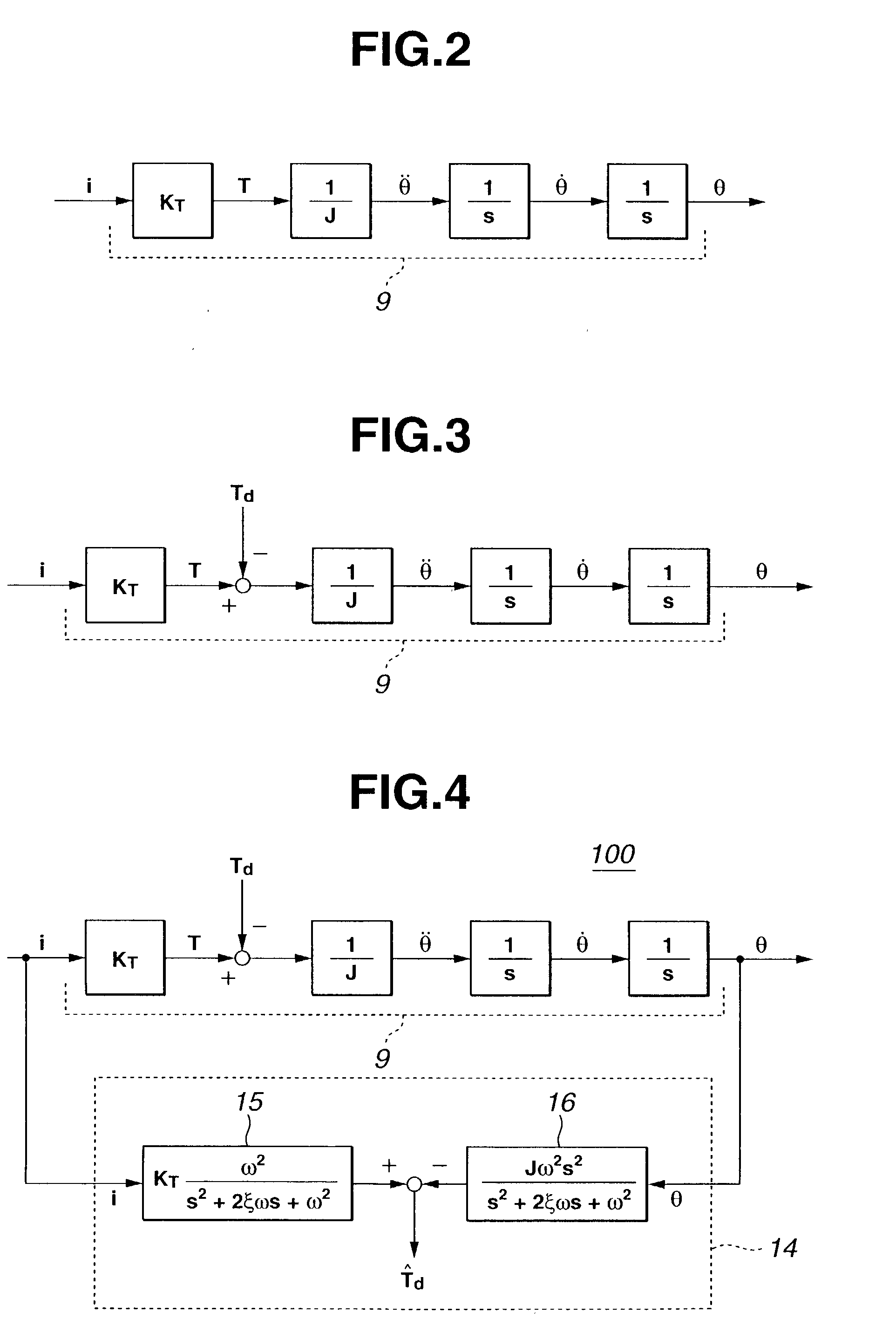
[0019] Referring to FIG. 1, there is schematically shown a vehicle steering control system 100 of a first embodiment of the present invention, which is practically applied to a front wheel steering system installed in a motor vehicle.

[0020] In the drawing, denoted by numeral 1 is a steering wheel, 2 is a steering reaction force actuator, 7 is a steering motor drive section, 9 is a steering motor, 10 is a steering gear unit, 11a and 11b are tie rods, 12 is an encoder, 14 is a road surface disturbance estimation section, 18 is a road surface disturbance based steering reaction force calculating section (or a second steering reaction force calculating section), 21 is a vehicle behavior based steering reaction force calculating section (or a first steering reaction force calculating section), 22 is an instruction current calculating section and 28 is a final steering reaction force calculating section.

[0021] The steering wheel 1 is a device that is handled by a driver. That is, when ste...


PUM


Abstract

In a steering mechanism of steer-by-wire type which includes a first steering unit that is handled by a driver and a second steering unit that steers steered road wheels with the aid of a steering motor, there is employed a control system which input and output detecting sections that detect input and output of the steering motor, a road surface disturbance estimating section that estimates a disturbance of road surface based on both the detected input and output of the steering motor, and a steering reaction force calculating section that, based on the estimated disturbance of road surface, calculates a steering reaction force that is to be applied to a steering wheel of the first steering unit.

Description

BACKGROUND OF INVENTION[0001] 1. Field of Invention[0002] The present invention relates to vehicle steering control systems, and more particular, to the systems of a so-called "steer-by-wire type" wherein a first steering unit that is handled by a driver and a second steering unit that steers steered road wheels are not connected through a linkage mechanism, that is, the steered road wheels are steered by a powered actuator in accordance with an information signal issued from a sensor associated with a steering wheel.[0003] 2. Description of Related Art[0004] One steering control system of the steer-by-wire type is shown in Japanese Laid-open Patent Application (Tokkaihei) 11-78947. In this system, for steering the steered road wheels, there are employed an electric motor that produces a power to steer the steered road wheels, sensing devices that sense an angle of rotation of the steering wheel and a steering torque of the same and a steering reaction force generating device that i...

Claims


Application Information

Patent Timeline
Patent Type & Authority Applications(United States)
IPC IPC(8): B62D6/00B62D5/04B62D101/00B62D111/00B62D113/00B62D119/00B62D137/00
CPCB62D6/008
Inventor UENUMA, KENYAMOURI, HIROSHI
Owner NISSAN MOTOR CO LTD
Why Eureka
Try Eureka