Process variable identification method, process variable identification apparatus, and evaluation sample

Inactive Publication Date: 2003-03-20
RENESAS TECH CORP
View PDF0 Cites 2 Cited by
  • Summary
  • Abstract
  • Description
  • Claims
  • Application Information

AI Technical Summary

Problems solved by technology

In the above-described method, a large area is required for the TEG, and there is also a problem that accurate evaluation is impossible since a sampling error of a material constant (effective dielectric constant) is determined by the measurement accuracy of a very thin interlayer insulating film.
However, measuring a material constant of an insulating film formed between pitch wirings has been conventionally impossible.
Furthermore, although the wiring structure can

Method used


Image

  • Process variable identification method, process variable identification apparatus, and evaluation sample
  • Process variable identification method, process variable identification apparatus, and evaluation sample
  • Process variable identification method, process variable identification apparatus, and evaluation sample

Examples


second example

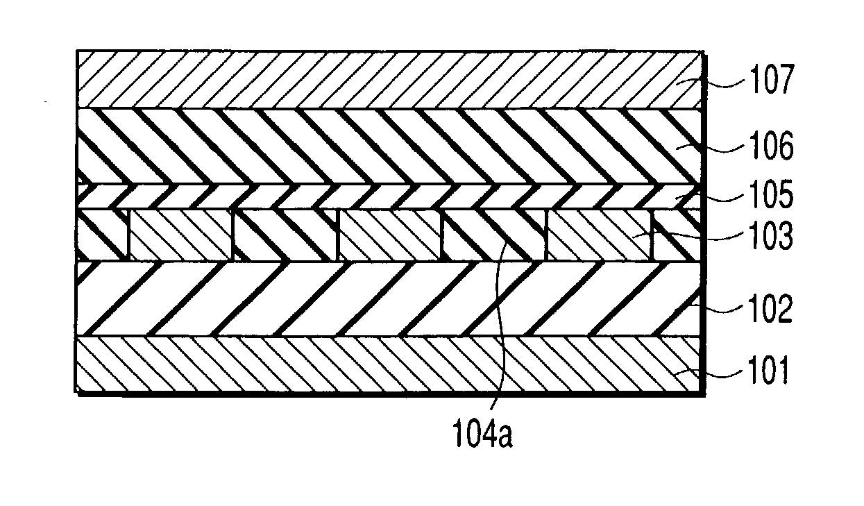
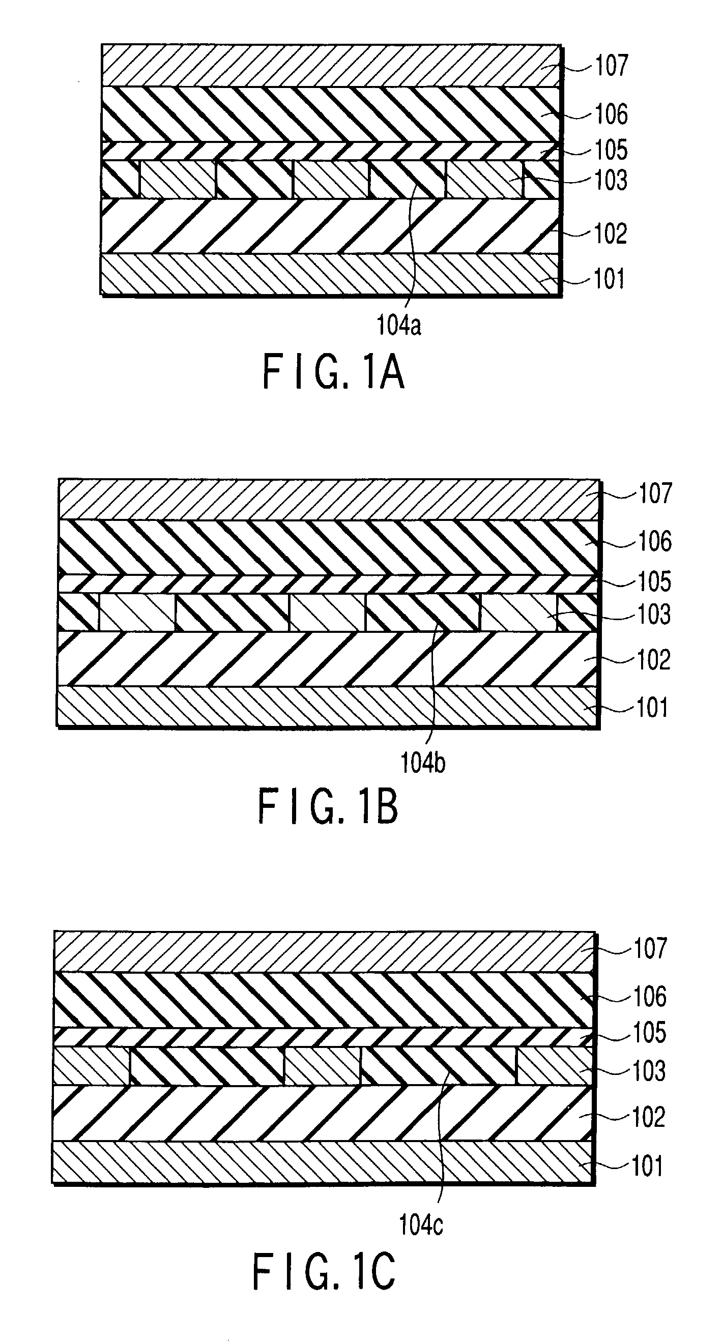
[0079] FIGS. 9A and 9B are views shwoing an example of the structure of the second wiring layer of the TEG samples shown in FIGS. 1A to 1C. As shown in FIGS. 9A and 9B, this example is characterized in that there are generated two types (2L and 2L') of the TEG samples having different overlapping lengths (opposing lengths) of the wiring 703a (703a') and the wiring 703b (703b'). It is to be noted that the width and the pitch of the respective wirings are the same.

[0080] By taking a difference in the capacity Cij obtained from the both TEG samples, it is possible to obtain the capacity Cij in which the parasitic effect of the external wirings and the bonding pad is completely removed.

[0081] As a result, in the forgoing embodiment and the first example, a relatively long opposing length is required in order to minimize the influence of the above-descried parasitic effect. According to this embodiment, however, the opposing length of the second wiring layer can be shortened, and the eff...

third example

[0082] FIGS. 10A to 10C are views showing the structure of the TEG according to a third example of the present invention. In the above-described embodiment, there is provided the TEG in which the intervals of the pitch wirings are designed to be equal and the wiring widths are different from each other.

[0083] In this example, the wirings widths W of the second wiring layers 103a to 103c are different from each other in accordance with each of three samples, and a quantity of total displacement .DELTA.W of the wiring width is determined as a process variable. In this example, since the measurement values of the capacities C12 and C23 can be increased, the measurement accuracy of the film thicknesses T1, T3 and T4 and the dielectric constants .epsilon.1, .epsilon.3 and .epsilon.4 can be improved.

fourth example

[0084] FIGS. 11A and 11B are views shwoing an example of the structure of the second wiring layer of the TEG samples shown in FIGS. 1A to 1C. In this example, each second wiring layer 1003 is connected to a common electrode 1001. As a result, although two electrode outgoing lines 2a and 2b are required with respect to the second wiring layer 103 in the second example, one line can suffice, thereby reducing a pad area. In this embodiment, since C22 is not measured, a number of TEGs must be increased instead.


PUM


Abstract

The present invention includes calculating an inter-wiring capacitance from process variables including a structural variable and a material constant of each interlayer insulating film in a multi-wiring structural including a first wiring layer, a second wiring layer having a pluraltiy of pitch wirings with a width W arranged at a pitch P, a third wiring layer and a pluraltiy of interlayer insulating films which insulate and separate the first to third wiring layers from each other, modeling a function expression in which the process variables are determined as variables and the inter-wiring capacitance is determiend as a response variable from the relationship between the obtained inter-wiring capacitance and the process variables, creating actual multi-layer wiring structures and measuring an inter-wiring capacitance from each created multi-layer wiring structure, and identifying the process variables of the actually formed multi-layer wiring structure from the measured inter-wiring capacitances based on the modeled function expression.

Description

[0001] This application is based upon and claims the benefit of priority from the prior Japanese Patent Application No. 2001-283932, filed Sep. 18, 2001, the entire contents of which are incorporated herein by reference.[0002] 1. Field of the Invention[0003] The present invention relates to a process variable identification method and a process variable identification apparatus used for obtaining a structure constant and a material constant of an interlayer insulating film in a multi-layer wiring structure, and an evaluation sample used in this process variable identification method.[0004] 2. Description of the Related Art[0005] A calculation of an inter-wiring capacity has been conventionally carried out by performing two-dimensional or three-dimensional field analysis with respect to various kinds of wiring structures. In this occasion, an effective dielectric constant, a film thickness and an electrode shape of an interlayer insulating film, and a three-dimensional shape in case ...

Claims


Application Information

Patent Timeline
IPC IPC(8): H01L21/66G06F17/50H01L21/00H01L21/3205H01L21/82H01L21/822H01L23/52H01L27/04H01L29/00
CPCG06F17/5036G06F30/367H01L21/00
Inventor MASUDA, HIROO
Owner RENESAS TECH CORP
Why Eureka
Try Eureka