Holder for optical loopback assembly with release mechanism

a technology of latch actuator and release mechanism, which is applied in the direction of optics, instruments, optical light guides, etc., can solve the problems of difficulty in accessing latch actuators and exerting sufficient manual force to depress latch actuators, and achieve the effect of convenient unlatching a duplex

Inactive Publication Date: 2003-04-03
WOODHEAD IND INC
View PDF5 Cites 109 Cited by
  • Summary
  • Abstract
  • Description
  • Claims
  • Application Information

AI Technical Summary

Benefits of technology

0010] When the pull member is pulled by the user, it rotates the release latch which, in turn, rotates to depress the latch arms of the loopback assemblies to unlatch or disconnect position. When the latch arms are depressed by the release latch, the loopback assemblies can be removed from their associated end connectors by convenient manipulation of the holder.
0011] Thus, with the device of the present invention, the user may conveniently unlatch a duplex loopback assembly simply by pulling a readily accessible pull member outwardly of the end of the cover and extending longitudinally in the direction of the cover. The design obviates the need to manipulate the fingers of the user into position between tightly spaced adjacent holders.

Problems solved by technology

There is a problem with the existing release mechanism described above in that the latch arms of the release mechanisms are located to one side of the handle, and the handles are arranged in close side-by-side relation with the latch actuator positioned immediately adjacent to another holder.
This requires the user to place his or her fingers between two closely spaced holders, making it difficult to access the latch actuators and then to exert sufficient manual force to depress the latch actuator because there is insufficient room to do so.

Method used


Image

  • Holder for optical loopback assembly with release mechanism
  • Holder for optical loopback assembly with release mechanism
  • Holder for optical loopback assembly with release mechanism

Examples


Embodiment Construction

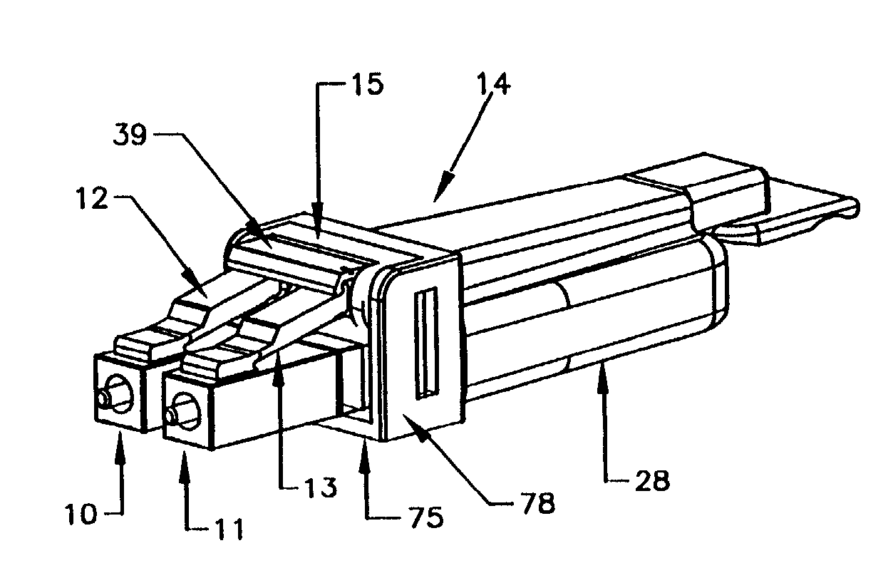
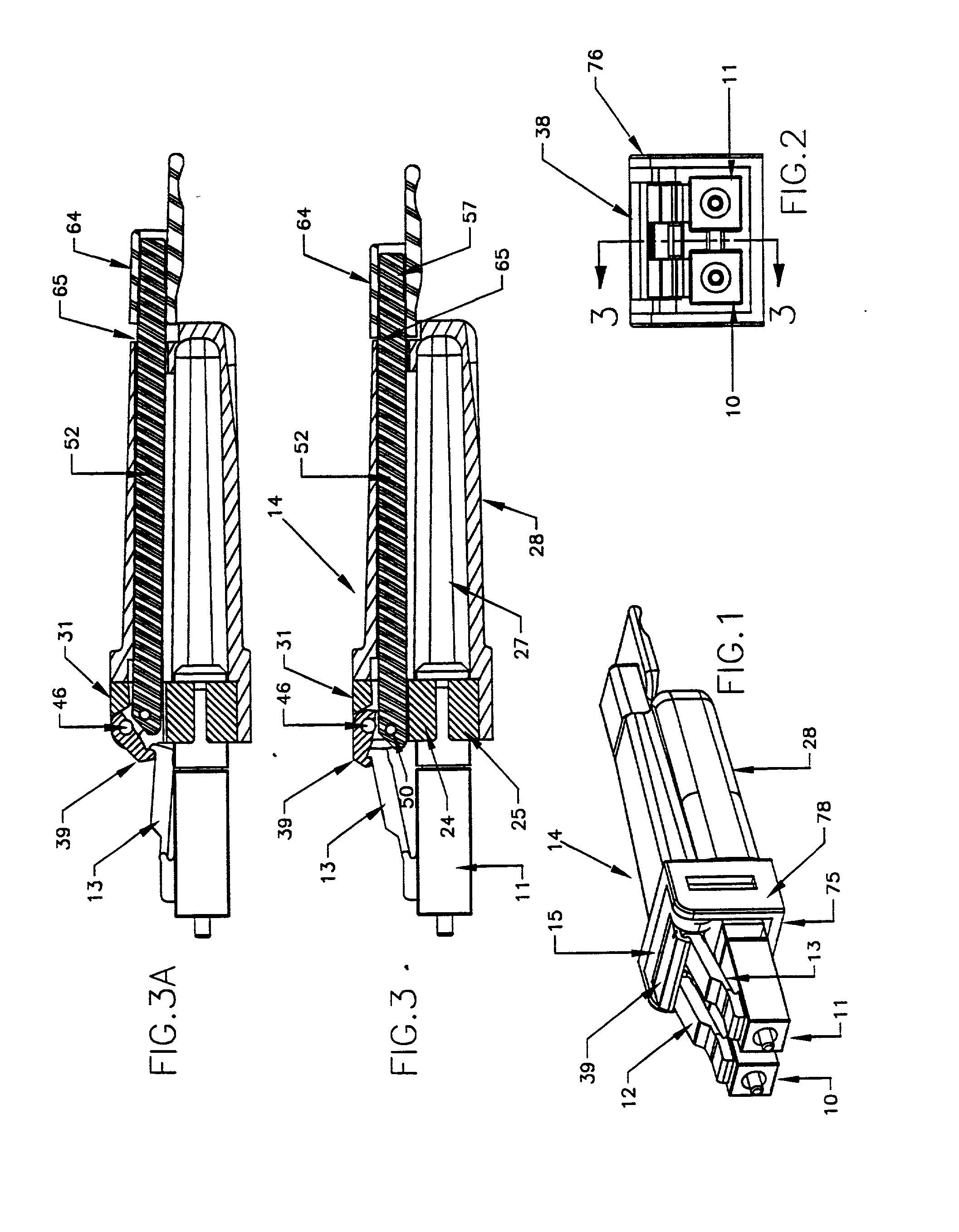
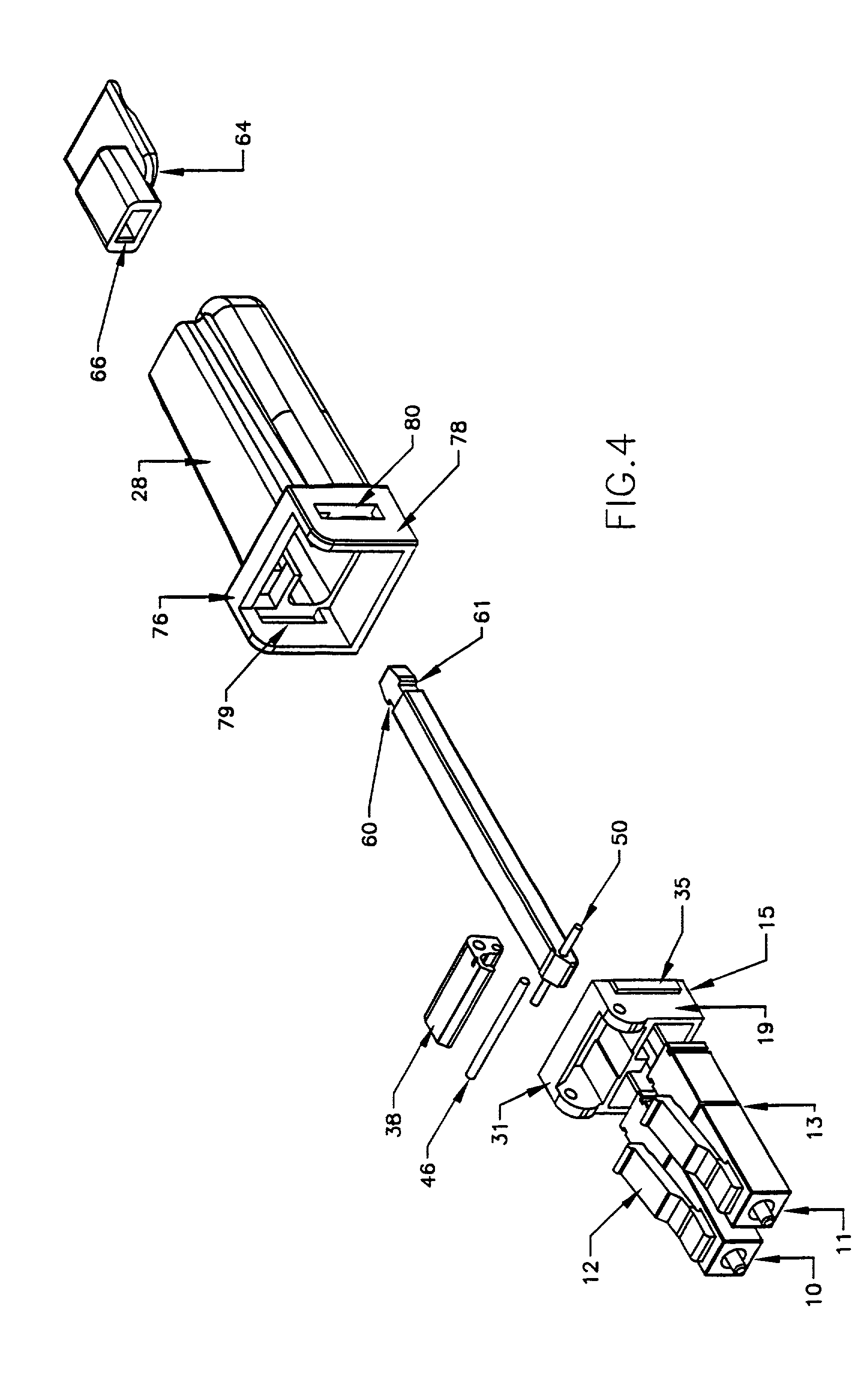
[0024] Referring first to FIGS. 1-3, reference numerals 10 and 11 refer generally to a pair of conventional loopback assemblies in the form of LC connectors 10, 11. The connectors 10, 11 are each associated with a mating connector which is also conventional and is not shown in the drawing. The mating connector or "end" connector as it is sometimes referred to, is assembled to a conventional fiber optic transmission medium.

[0025] The LC connectors 10, 11 are conventionally provided with latch arms such as those designated 12, 13 respectively. As best seen in FIG. 3, the latch arm 13 extends rearwardly and upwardly. The latch arms 12, 13 are biased to the upward position shown in FIG. 3, sometimes referred to as the latched position; and they may be depressed downwardly to a release position (seen in FIG. 3A). In the latched position, the LC connectors are rigidly connected to their associated mating connectors, and in the release position, the LC connectors may be removed rearwardly ...


PUM


Abstract

A duplex holder for an optical loopback assembly includes a clip adapted to receive and hold an optical loopback assembly. The clip is mounted in an elongated cover which provides a handle for manipulating the holder. A release latch pivotally mounted to the clip engages release arms on the loopback assembly. An elongated member is pivotally connected to the release latch and extends beyond the rear end of the cover so that it is accessible by a user from the rear of the cover. When the elongated member is translated, it rotates the release latch to move the latch arm of the loopback assembly to a release position so that the loopback assembly can be removed from its associated mating connector by convenient manipulation of the holder.

Description

[0001] The present invention relates to holders for optical loopback assemblies; and in particular, it relates to a holder with a release mechanism.[0002] Fiber optic cables provide a transmission medium for data in many applications, for example, in commercial Automatic Teller Machines commonly used in banks. In many cases the fiber optic cable is coupled to an electronic data storage unit. Tests are routinely made both of the storage unit and the optical cables associated with it.[0003] In order to facilitate testing of the system or components of such a system employing fiber optic cables, it has been the practice to arrange the fiber optic cables in a bundle and extend them to a common area where the ends of the cables are provided with devices referred to as "loopback assemblies" or attenuators. A loopback assembly is a device which receives the optical signal along one path and redirects the signal back into the transmitting medium with a pre-determined attenuation level. In a...

Claims


Application Information

Patent Timeline
Patent Type & Authority Applications(United States)
IPC IPC(8): G02B6/38
CPCG02B6/3845G02B6/3825
Inventor FILLION, MARK E.JORDY, STEVE DEVANKOV, ANDREI A.
Owner WOODHEAD IND INC
Why Eureka
Try Eureka