Method of utilization a flow energy and power installation for it

a technology of flow energy and power installation, which is applied in the direction of machines/engines, toys, transportation and packaging, etc., can solve the problems of tidal power plants not being economically feasible as primary electricity sources, relative inefficiency, and small conversion of pumps

Inactive Publication Date: 2003-04-10
BOLONKIN ALEXANDER ALEXANDROVICH
View PDF0 Cites 78 Cited by
  • Summary
  • Abstract
  • Description
  • Claims
  • Application Information

AI Technical Summary

Problems solved by technology

Relatively inefficient, these pumps convert only a small portion of the wind stream energy to work as it passes through the rotor.
Thus far, tidal power plants have not been economically feasible as a primary electricity source because of their intermittent power generation and their high construction costs.
1. Wind energy is distributed in space. It has small energy density. We cannot place big turbines on the ground. Many small turbines must be used instead. In California, there are thousands of small wind turbines. Big turbines do not produce

Method used


Image

  • Method of utilization a flow energy and power installation for it
  • Method of utilization a flow energy and power installation for it
  • Method of utilization a flow energy and power installation for it

Examples


Embodiment Construction

Method

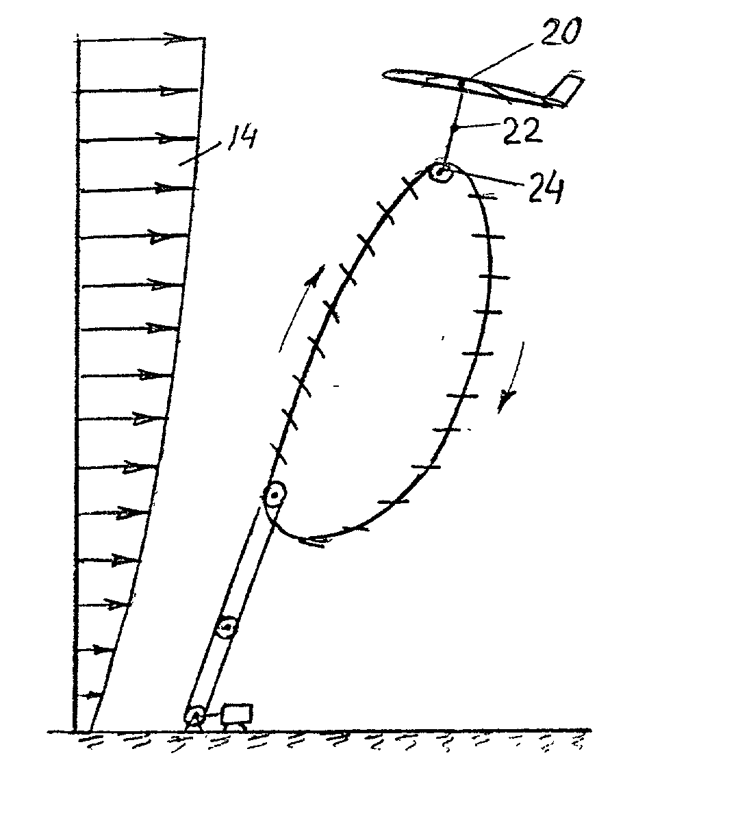
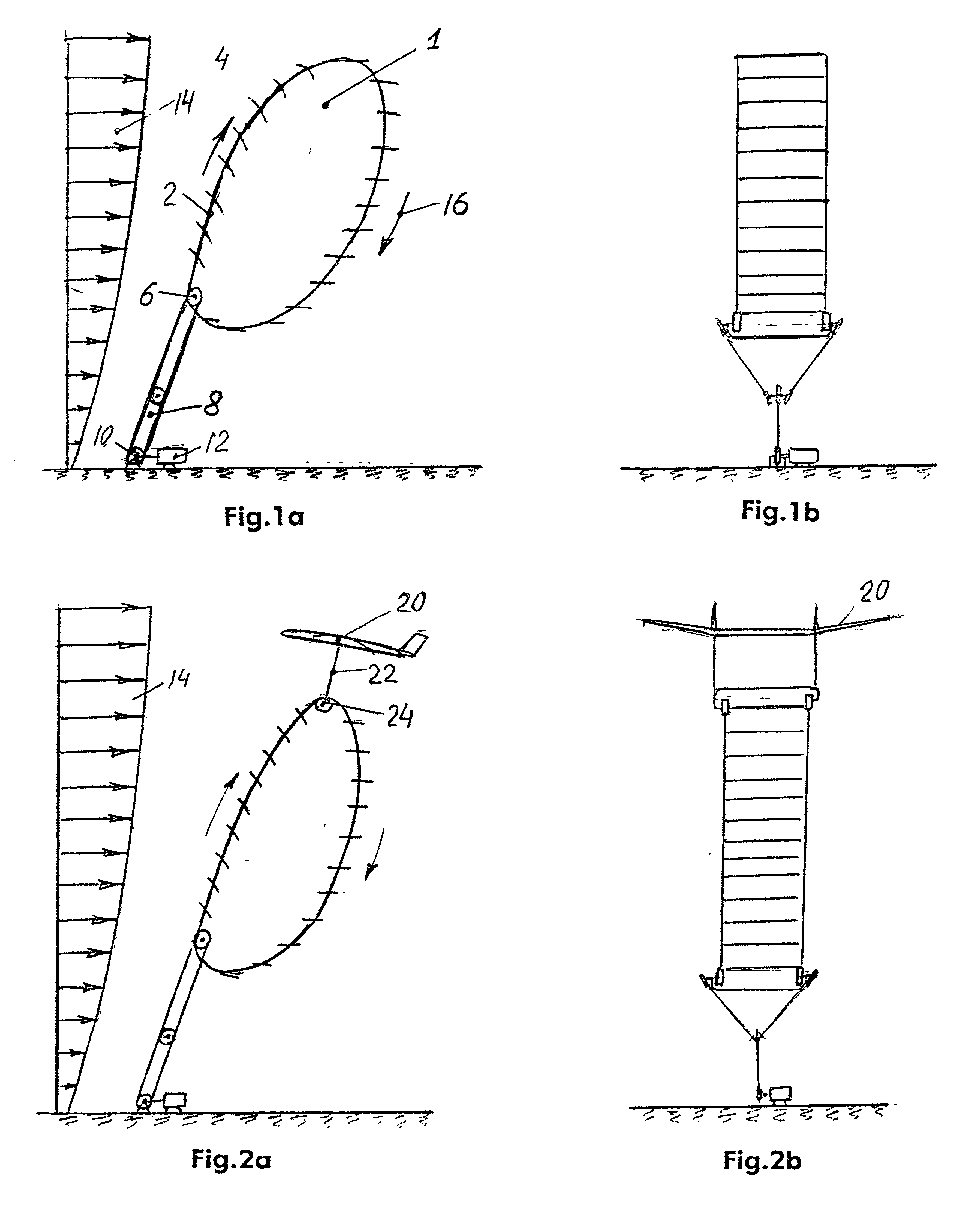
[0128] The present invention relates, in general, to methods and facilities for the utilization of a flow (air, water) energy. The purpose is to dramatically increase the power capacity of a single installation and decrease the cost per unit of power. Author suggests use as a big flexible rope-blade free-flying rotor disposed at high altitude or in a stream of water (sea, ocean, river, etc.).

[0129] 1. A Method of Utilization of a flow (stream) energy, comprising the following steps:

[0130] (a) connecting lift-drag devices to a rotor;

[0131] (b) connecting said rotor to the ground, with a connecting rope;

[0132] (c) disposing energy conversion station at the Earth surface;

[0133] (d) connecting said rotor to said energy conversion station with rope transferor;

[0134] (e) disposing said rotor to work as a free-fly (free-float) rotor;

[0135] (f) transferring rotational energy from said rotor to said energy station-with said rope transferor;

[0136] (g) controlling the altitude and power ...


PUM


Abstract

The author suggests a new method and a new inexpensive, large blade-rope type wind rotor, that will be suspended at high altitude and produce huge quantities of energy. The air installation embodiment includes (FIG. 25): propeller 220, wing 226, rope transmission 229, electric generator 12 located at ground. Water rotors can utilize energy of ocean and sea streams. The invention contains 11 projects: 6 for air, 1 for a river, 3 for the sea and ocean, and 1 for ships. They have a power capacity of up to 60 MgW (air), up to 200 MgW (water) for one unit. The suggested installations have the following advantages: 1. Huge power production capacity-up to 5000-10000 times more than conventional ground-based rotor designs. 2. The rotor operates at high altitude of 1-14 kilometers, where wind has high speed and high stability (permanent flows). 3. The installation is much less expensive compared to conventional currently-employed windmills, partly because no tower is necessary to fix the rotor in space. 4. Wind energy is free -environmentally friendly.

Description

GROSS-REFERENCE TO RELATED APPLICATIONS[0001] Not ApplicableREFERENCE TO A MICROFICHE APPENDIX[0002] Not Applicable[0003] 1. Field of the Invention[0004] The present invention relates, in general, to methods and facilities for the utilization of flow (air, water) energy. The purpose is to dramatically increase the power capacity of a single installation and to decrease its cost per unit of power. The author suggests using a big flexible rope-blade free-flying rotor disposed at high altitude or in a water (sea) stream. The author also suggests using a rope device to transfer energy from the rotor to an electric generator.[0005] 2. Description of the Related Art[0006] WIND POWER. Wind is a clean and inexhaustible source of energy that has been used for many centuries to grind grain, pump water, propel sailing ships, and perform other work. The amount of wind power available, however, varies depending upon the weather. Thus the windmills used to pump water have been largely replaced by...

Claims


Application Information

Patent Timeline
IPC IPC(8): A63H27/08F03D5/00F03D11/04
CPCA63H27/08F03D5/00F03D11/04Y02E10/728F05B2240/921Y02E10/70F05B2210/16F03D13/20Y02E10/72F03D9/32F03D9/25F03D80/70
Inventor BOLONKIN, ALEXANDER ALEXANDROVICH
Owner BOLONKIN ALEXANDER ALEXANDROVICH
Why Eureka
Try Eureka