Dynamic voltage control method and apparatus

a voltage control and dynamic technology, applied in the direction of generating/distributing signals, multi-programming arrangements, high-level techniques, etc., can solve the problems of power consumption significantly affecting the utility of these devices, conventional power control methods may not consider the different power demands of the processor, and may contribute to the length of tim

Inactive Publication Date: 2003-04-17
MEDIATEK INC
View PDF3 Cites 134 Cited by
  • Summary
  • Abstract
  • Description
  • Claims
  • Application Information

AI Technical Summary

Benefits of technology

0006] One embodiment according to the present invention includes a method of dynamic power control in a system having at least one processor, the at least one processor including at least one clock signal capable of operating at a plurality of frequencies. The method comprises acts of determining a clock frequency requirement of the at least one processor, determining a voltage requirement to support the clock frequency requirement, operating the at least one clock signal according to the clock frequency requirement, and providing a voltage to supply the at least one processor according to the voltage requirement.
0007] Another embodiment according to the present invention includes a processor including at least one clock signal operating at a plurality of frequencies. The processor comprises one or more clocked components receiving the at least one clock signal, and a controller coupled to at least one of the components to determine a clock frequency requirement of the processor, the controller adapted to determine a voltage requirement based on the clock frequency requirement of the processor and to sequence a transition to a power state defined by the clock frequency requirement and the voltage requirement.
0008] Another embodiment according to the present invention includes a controller to dynamically control the power to a processor. The controller compr

Problems solved by technology

In battery powered devices such as cellular phones, laptop computers, person digital assistants (PDAs), and other portable and handheld devices, power consumption may be a significant contributor to the length of time during which a device may operate before the device must either be recharged and/or connected to an alternate power source.
As such, power consumption may significantly impact the utility of these devices.
However, the processor in a digital dev

Method used


Image

  • Dynamic voltage control method and apparatus
  • Dynamic voltage control method and apparatus
  • Dynamic voltage control method and apparatus

Examples


Embodiment Construction

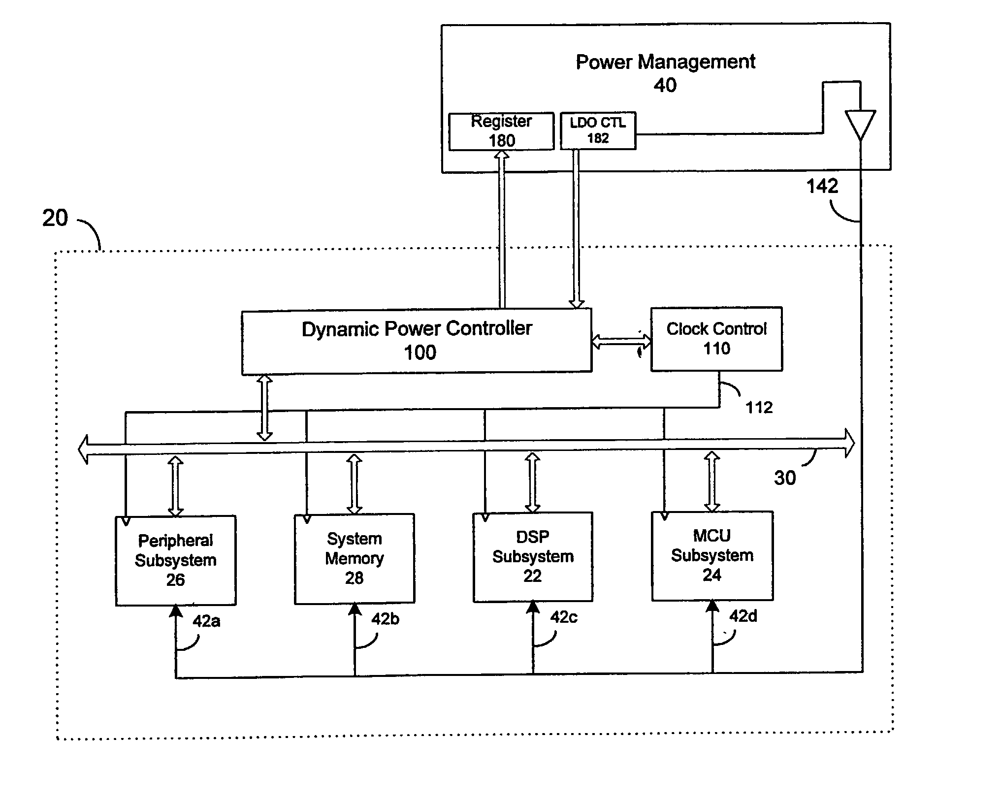
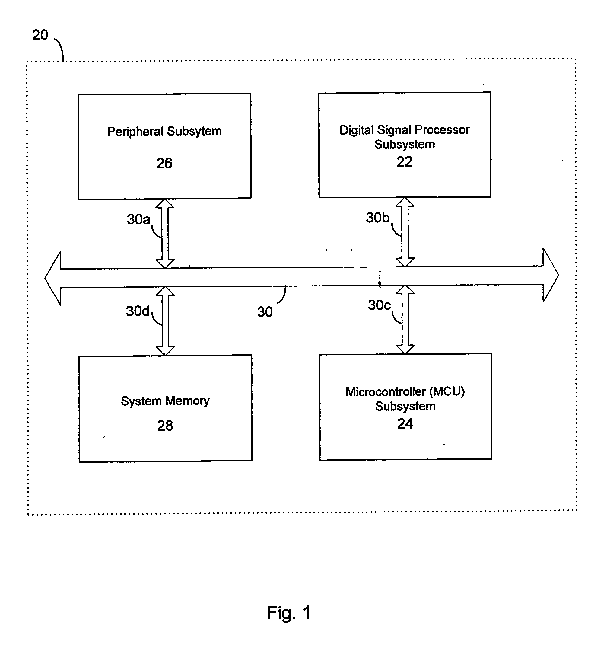
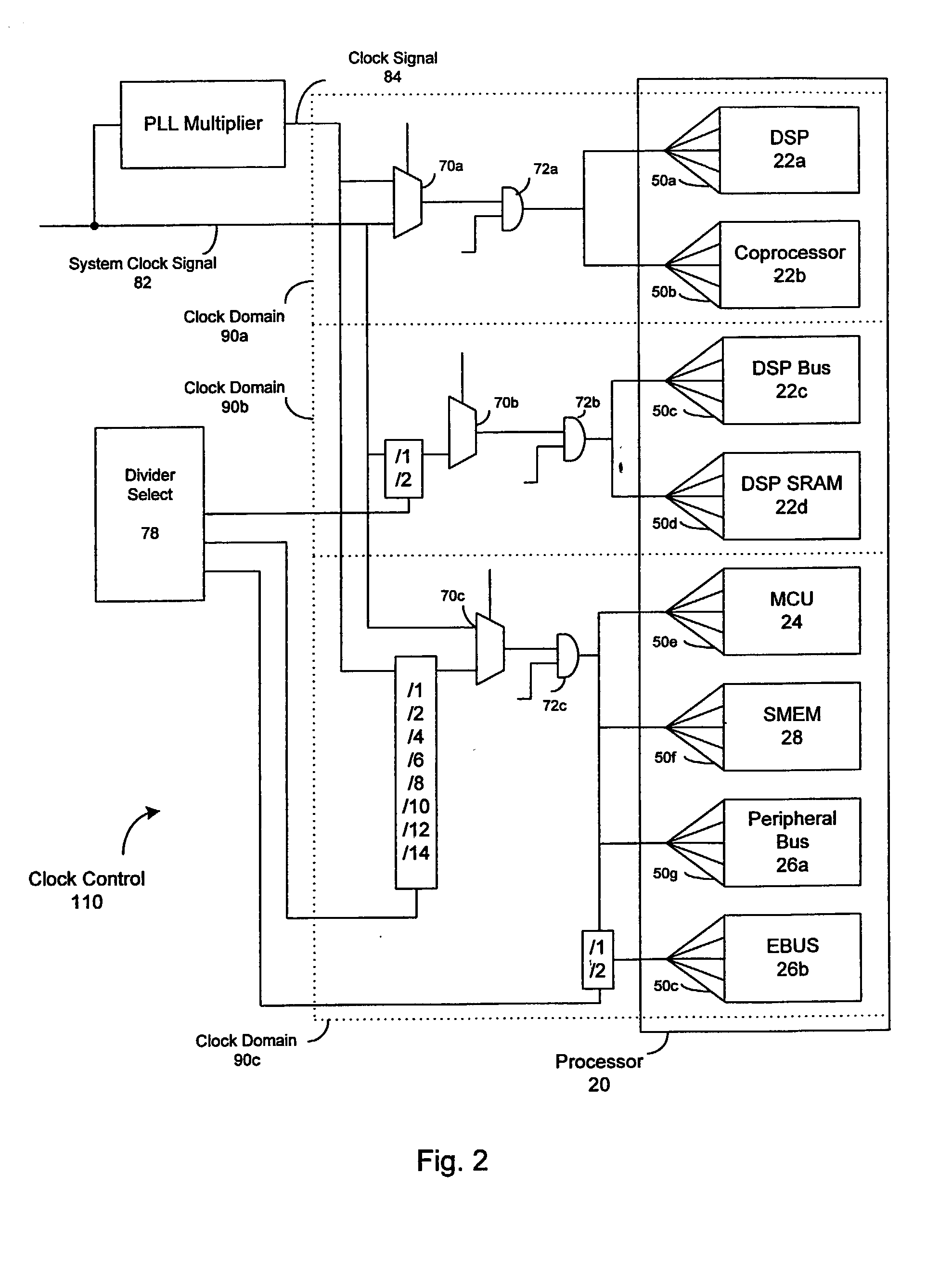
[0017] In many devices, particularly battery powered devices, it is advantageous to reduce the amount of time in which the device's processor is consuming excess power. A processor is considered to be consuming excess power when the computational tasks, functions, and operations of the processor may be performed, and / or the processing demands met, at a lower power state. The term "processor" refers, generally, to any apparatus that performs logic operations, computational tasks, control functions, etc. A processor may include one or more subsystems, components, and / or other processors. A processor will typically include various logic components that operate using a clock signal to latch data, advance and / or sequence logic states, synchronize computations and logic operations, and / or provide other timing functions.

[0018] Applicant has observed that the power consumption of a device is related to the square of the voltage supplied to the device's processor and proportional to the freq...


PUM


Abstract

A dynamic power controller is provided that identifies a clock frequency requirement of a processor and determines a voltage requirement to support the clock frequency requirement. The dynamic power controller transitions the processor to a power state defined by the clock frequency requirement and the voltage requirement. In particular, a voltage level indicated by the voltage requirement is supplied to the processor and the frequency distribution indicated by the frequency requirement is provided to the clocks signals of the processor.

Description

[0001] This application claims the benefit of U.S. Provisional Application 60 / 315,655 under 35 U.S.C. .sctn.119(e) filed Aug. 29, 2001, entitled "DIGITAL BASEBAND PROCESSOR," by Allen, et al. The entirety of the above provisional application is hereby incorporated by reference.FIELD OF THE INVENTION[0002] This invention relates to reducing the power consumption in processors and, more particularly, to methods and apparatus for dynamically controlling the voltage level supplied to a processor based on the processing state and / or computational demands of the processor by determining the clock frequency requirement and a corresponding voltage requirement of the processor.BACKGROUND OF THE INVENTION[0003] Power consumption and management is a design concern for developers of processors, digital devices, computer systems etc. In battery powered devices such as cellular phones, laptop computers, person digital assistants (PDAs), and other portable and handheld devices, power consumption m...

Claims


Application Information

Patent Timeline
IPC IPC(8): G06F9/30G06F1/04G06F1/08G06F1/32G06F9/38G06F9/46G06F9/48G06F11/28G06F11/36G06F12/00G06F12/02G06F12/08G06F13/28G06F13/38G06F13/42H03L7/08H03L7/095H03L7/183H04B1/40
CPCG06F1/04G06F9/3869G06F1/3203G06F1/3237G06F1/324G06F1/3287G06F1/3296G06F9/3836G06F9/3851G06F9/4843G06F11/3636G06F12/0842G06F12/0859G06F13/28G06F13/385G06F2213/3814H03L7/0802H03L7/095H03L7/183H04W88/06Y02B60/1217Y02B60/1221Y02B60/1282Y02B60/1285Y02B60/144Y10S331/02Y02B60/1235Y02B60/32G06F1/08Y02D10/00Y02D30/50Y02D30/70
Inventor SOERENSEN, JOERNALLEN, MICHAELBIRK, PALLE
Owner MEDIATEK INC
Why Eureka
Try Eureka