
Adaptive radiated emission control

a technology of radiated emission and control, applied in the direction of pulse manipulation, pulse technique, transmission/receiving by adding signal to wave, etc., can solve the problems of unintentional radiated emission from power line communication system, data transmission over power line, and inability to control radiated emission in the normal case of worse-case installations in office and home powerline networks, so as to limit radiated emission

Inactive Publication Date: 2003-04-17
ENIKIA
View PDF7 Cites 27 Cited by
  • Summary
  • Abstract
  • Description
  • Claims
  • Application Information

AI Technical Summary

Benefits of technology

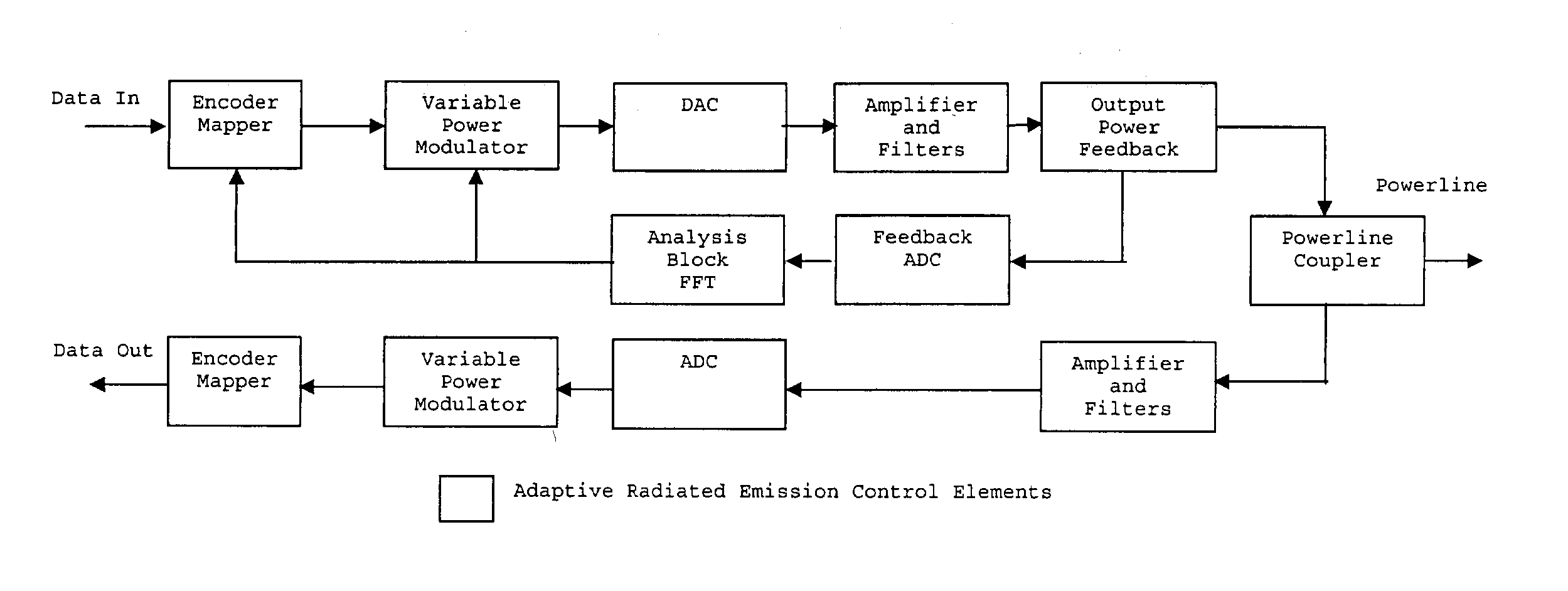
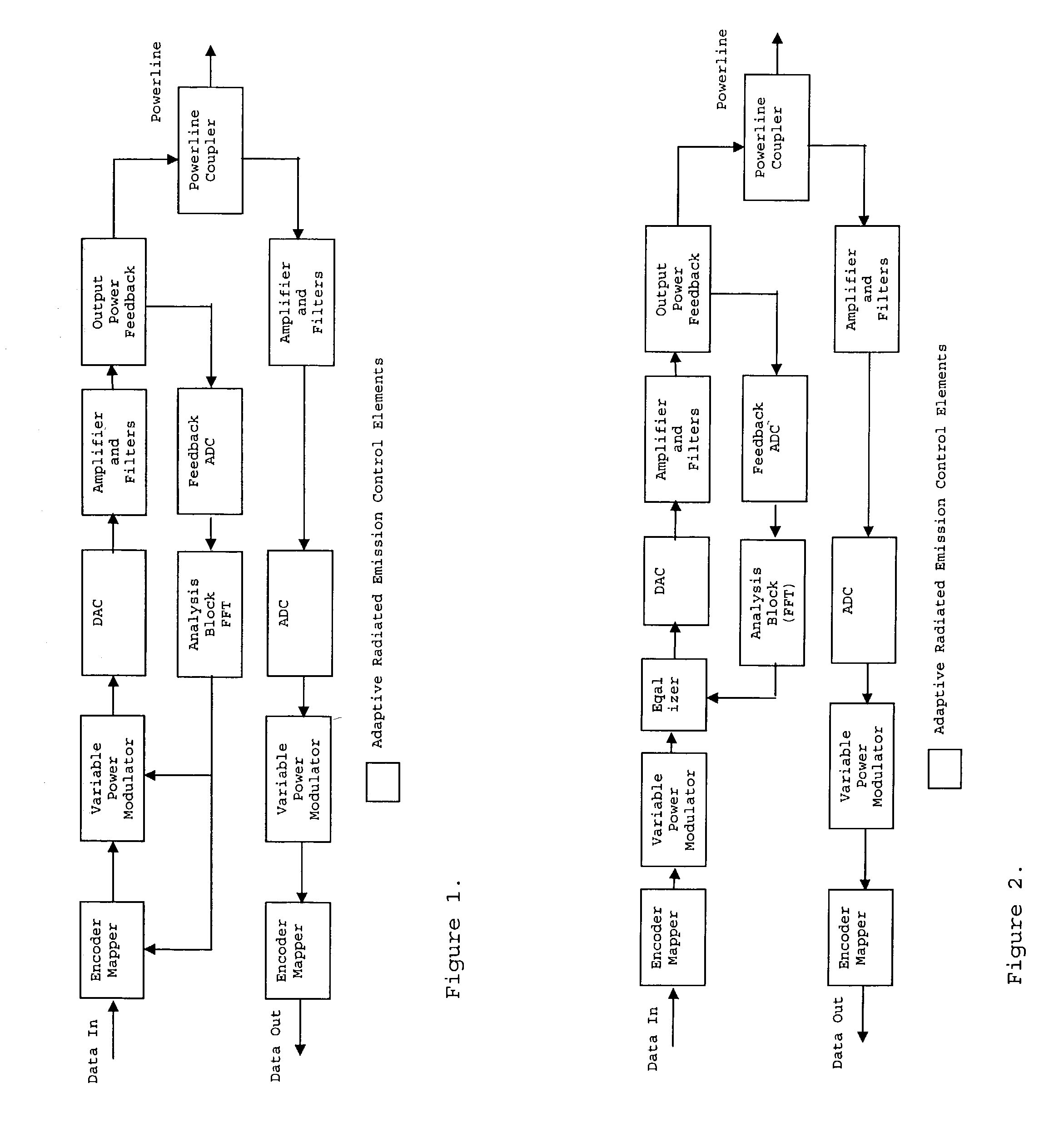
0015] In yet another embodiment of the invention, an adaptive radiated emission control includes an equalizer instead of a var

Problems solved by technology

However, powerline networks were originally designed for optimal delivery of electricity and not for data signals.
Highly variable and unpredictable levels of impedance, signal attenuation, noise and, generally, radiated emission may create an extremely harsh environment that makes data transmission over power lines challenging.
Radiated emissions from a power line communication system are, of course, unintentional.
It was observed that installations in offices and homes (in-home powerline network) are typically worse case environments for controlling radiated emissions.
The complexity of this antenna is further complicated when one considers the dynamic (i.e. time varying) nature of the discontinuities.
Impedance discontinuities are caused by wire nut connections, switches, wall socket outlets and appliance loads.
These identified problems tend to make prediction and modeling of radiated emissions from power line communication networks very difficult.
However, for a multi-carrier or OFDM communication system, reducing the power for all carriers affects the performance of carriers that do not cause excessive levels of radiated emissions.

Method used


Image

  • Adaptive radiated emission control
  • Adaptive radiated emission control

Examples


Embodiment Construction

[0021] FIG. 1 shows one embodiment for adaptive controlling of radiated emissions according to the invention which utilizes encoder, mapper, and a modulator with variable power features. For a multi-carrier and / or OFDM (Orthogonal Frequency Division Multiplexing) system, the modulator adjusts the power of each carrier based on the information provided by the feedback analysis block. The encoder and mapper block takes into account the information provided by the feedback analysis block for the purpose of constructing a carrier mask, carriers which could not be compensated in the modulator could be entirely removed from the transmit signal. The feedback analysis block processes the feedback data received as the result of operation of the feedback circuit. The feedback circuit measures power output of the transmitter, in the most simplistic way, it could be accomplished by the measurement across the source resistor connected to the output of the transmit amplifier in series with the po...


PUM


Abstract

An adaptive radiated emission control includes measurement of the transmit power spectrum and feedback to a variable power modulator. The variable power modulator creates an adjusted output spectrum that limits radiated emissions. Alternatively, the variable power modulator may also be an equalizer to adjust the output spectrum.

Description

[0001] The benefit of priority of the provisional application No. 60 / 310,298 filed on Aug. 4, 2001 in the names of the inventors, is hereby claimed.[0002] 1. Field of the Invention[0003] The present invention relates to controlling radiated emissions for communications systems operating in a network with inconsistent and / or variable impedance. In particular, the invention can be used to control radiated emissions for communication systems operating over powerlines.[0004] 2. Description of the Related Art[0005] Although the principles of the invention can be used in connection with other communication systems, the invention will be described in connection with the power line communication systems of the type developed by Enikia, LLC. in New Jersey and described at pages 100-107 of the publication entitled "The Essential Guide to Home Networking Technologies" published in 2001 by Prentice-Hall, Inc., Upper Saddle River, New Jersey, described in copending applications filed Jun. 28, 20...

Claims


Application Information

Patent Timeline
IPC IPC(8): H04B3/54
CPCH04B3/542H04B2203/5495H04B2203/5416
Inventor MANIS, CONSTANTINE N.LOGVINOV, OLEGBAUTISTA, MIKE K.
Owner ENIKIA
Learn More