Method and coating system for coating substrates for optical components

Inactive Publication Date: 2003-05-01
CARL ZEISS SMT GMBH
View PDF6 Cites 7 Cited by
  • Summary
  • Abstract
  • Description
  • Claims
  • Application Information

AI Technical Summary

Benefits of technology

0077] The effectiveness of this annular shielding mask 127 when employed in the geometric arrangement shown will now be demonstrated, based on FIG. 7. FIG. 7 presents plots of the mean particle incidence angles .beta. that occur when coating concave, spherical, surfaces using a planetary-drive system 101 for the case where no masks are employed (curves a and b) and the case where a centered, annular, mask 127 is employed (curves c, d, and e) for various positions of the source 108 of material as a function of radial distance, or angular displacement .phi., from the center of the substrate involved. In computing these mean particle incidence angles, the local mean particle incidence angles at various points P on the spherical surface 111 of the substrate while the planetary drive was in motion were computed at time intervals of 0.01 second and then averaged. It may be seen that the position of the material source in the case of coating involving no masks (curve a, which has been computed for the case of a centered evaporator, and curve b, which has been computed for the case of an eccentricity offset of 100 mm) has only an extremely slight effect on mean particle incidence angles, which increase along a roughly parabolic curve with increasing radial distance, or angular displacement .phi., from the center of the substrate. A comparison of areas near the perimeters of coatings deposited on spherical surfaces for the case where the material source was shifted off-axis by as much as 50 mm and an annular mask was employed and the case where no annular mask was employed clearly indicates the effectiveness of the annular mask in reducing mean incidence angles. The curves c, d, and e correspond to eccentricity offsets of 1 mm, 50 mm, and 100 mm, respectively. For .phi.>20.degree., mean particle incidence angles may be reduced by about 12.degree. by e

Problems solved by technology

Flawed film-thickness distributions may have adverse effects, such as a falloff in the transmittances of lenses towards their perimeters, particularly in the case of systems that have sharply curved optical surfaces.
In the case of field-lens systems, these effects may be worsened by effects due to optical incidence angles.
Variations in the refractive indices of coating materials from the centers of coatings out to their perimeters have already been observed, particularly in the case of coatings on sharply curved optical surfaces, which also makes designing coatings difficult.
The radial decrease in packing density causes other problems, particularly in the case of systems that operate with short-wavelength ultraviolet light.
For example, porous coatings absorb more water than smooth coatings having superior packing densities, which may lead to transmission problems at, for example, wavelengths less than about 280 nm, in particular, at wavelengths of 157 nm or less, since UV-light having a wavelength of 157 nm is strongly absorbed by water, and coating-durabilit

Method used


Image

  • Method and coating system for coating substrates for optical components
  • Method and coating system for coating substrates for optical components
  • Method and coating system for coating substrates for optical components

Examples


Embodiment Construction

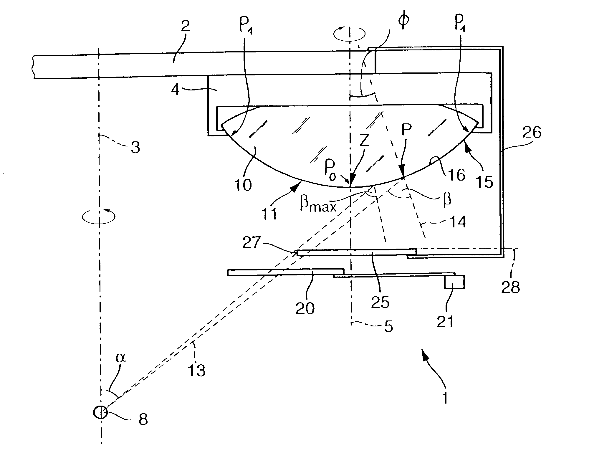
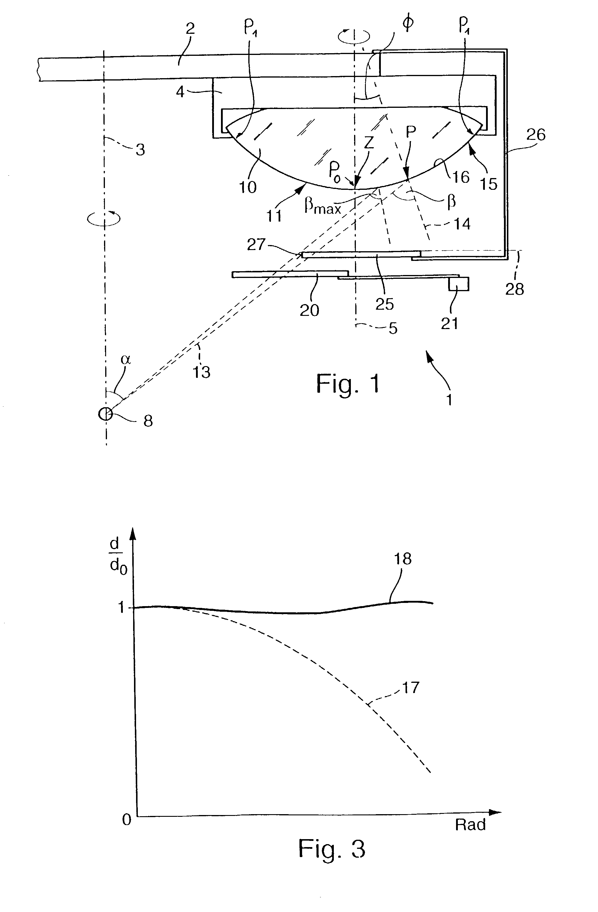
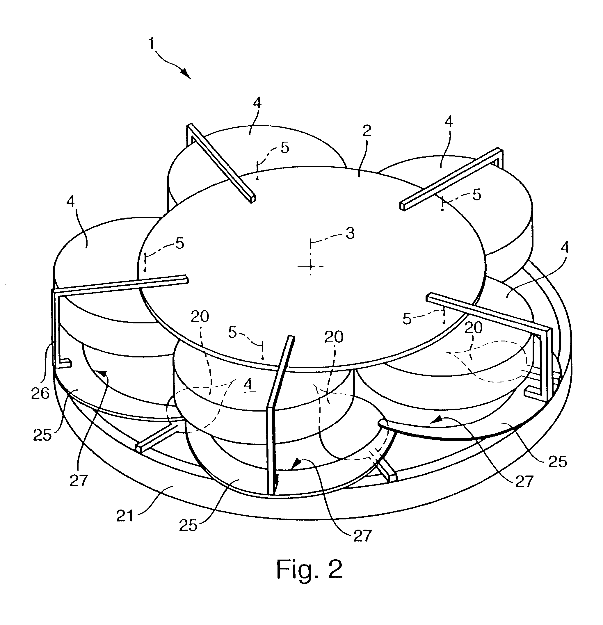
[0053] FIG. 1 schematically depicts the geometric arrangement of major components of an evaporation system with which optical components for microlithographic projection systems, in particular, lenses having sharply curved surfaces, may be coated using electron-beam evaporation methods or other PVD-methods, including sputtering, where the extension of the material source is preferably small compared to the coating system's dimensions, i.e. where the material source represents a quasi-point source. Since it may be desirable to simultaneously coat several substrates, which will normally be of similar type, under largely identical processing conditions on costing or technological grounds, the coating system has a planetary-drive system 1 situated within an evacuable coating chamber that is not shown here for moving the substrates to be coated during coating. This planetary-drive system has a nearly circular, disk-shaped, primary carrier 2 that is also termed a "planet carrier" and may ...


PUM

PropertyMeasurementUnit
Fractionaaaaaaaaaa
Fractionaaaaaaaaaa
Fractionaaaaaaaaaa

Abstract

A method for coating substrates (10) for optical components with essentially rotationally symmetric coatings employs a coating system equipped with a planetary-drive system (1) that has a rotating planet carrier (2) and several planets (4), each of which carries a single substrate, that corotate both with the planet carrier and with respect to the primary carrier. In one embodiment a set of stationary first masks (20) that allow controlling the radial variation in physical film thickness is arranged between a source (8) of material situated beneath the planets and the substrates. A set of second masks that mask off evaporation angles exceeding a limiting evaporation or incidence angle (betamax) for every substrate also corotate with the primary carrier (2), which allows depositing coatings having a prescribed radial film-thickness distribution and a virtually constant density of the coating material over their full radial extents for relatively low, and only slightly varying, evaporation angles.

Description

[0001] The following disclosure is based on German Patent Applications No. 101 46 192.5 filed on Sep. 17, 2001 and No. 102 37 430.9 filed on Aug. 12, 2002, which are incorporated into this application by reference.[0002] 1. Field of the Invention[0003] The invention relates to a method for coating substrates for optical components with essentially rotationally symmetric optical coatings and a coating system suitable for carrying out that method.[0004] 2. Description of the Related Art[0005] Optical systems that have a plurality of lenses that must be coated with rotationally symmetric optical coatings in order to reduce their reflectance or allow meeting other requirements are employed on projection systems for the microlithographic fabrication of semiconductor devices and other types of microdevices. If necessary, other optical components, such as the imaging mirrors employed on catadioptric or catoptric projection lenses, some of which may have sharply curved surfaces, will also h...

Claims


Application Information

Patent Timeline
IPC IPC(8): G02B1/11B05B13/02B05B15/04B05D1/32C03C17/245C23C14/04C23C14/50G02B1/10
CPCC23C14/044G02B1/10C23C14/505C23C14/0021
Inventor BAUER, HARRYHELLER, MATTHIASPAUL, HANS-JOCHENULLMANN, JENSSCHEIBLE, PATRICKZACZEK, CHRISTOPH
Owner CARL ZEISS SMT GMBH
Why Eureka
Try Eureka