Support apparatuses and jambs for windows and doors and methods of constructing same

a support apparatus and a technology for windows and doors, applied in the field of stud wall systems, can solve the problems of affecting the strength of the stud, the time-consuming process of the metal stud wall system, and the inability to replace the stud, etc., to achieve the effect of reducing the amount of time, preventing twisting, turning or bowing of the stud, and improving strength and rigidity

Inactive Publication Date: 2003-05-15
CLARKWESTERN DIETRICH BUILDING SYST
View PDF28 Cites 33 Cited by
  • Summary
  • Abstract
  • Description
  • Claims
  • Application Information

AI Technical Summary

Benefits of technology

[0018] Another embodiment of the present invention also provides an angled clip having a first portion with a cross-section generally similar to the cross section of the bridging / spacing member and a second portion lying in a plate extending approximately at a right angle to the first portion for attachment to the face of a wall or stud without passing through a conduit punch-out. The present invention may also provide a jamb connector for engaging the webs of two adjacent metal studs and for connection to bridging / spacing members on either side. The present invention may also include a hold down bracket attachable above a bridging / spacing member across a conduit punch-out to prevent removal of the bridging / spacing member.
[0019] Still another embodiment of the present invention comprises a stud bridging / spacing member for the quick and easy spacing of a plurality of studs without measuring, while at the same time providing bridging between the studs. In this embodiment, the bridging function of the stud bridging / spacing member reinforces the studs to resist bending under axial loads and to resist rotation under transverse loads, providing a "shear" connection between the bridging / spacing member and the studs. The stud bridging / spacing member enables a substantial reduction in the amount of time needed to install a metal stud wall and, in particular, a load bearing wall, while at the same time functioning effectively to lock each stud against bowing, twisting or turning when subject to axial, transverse and / or lateral loads, thereby providing improved strength and rigidity to the metal stud wall.
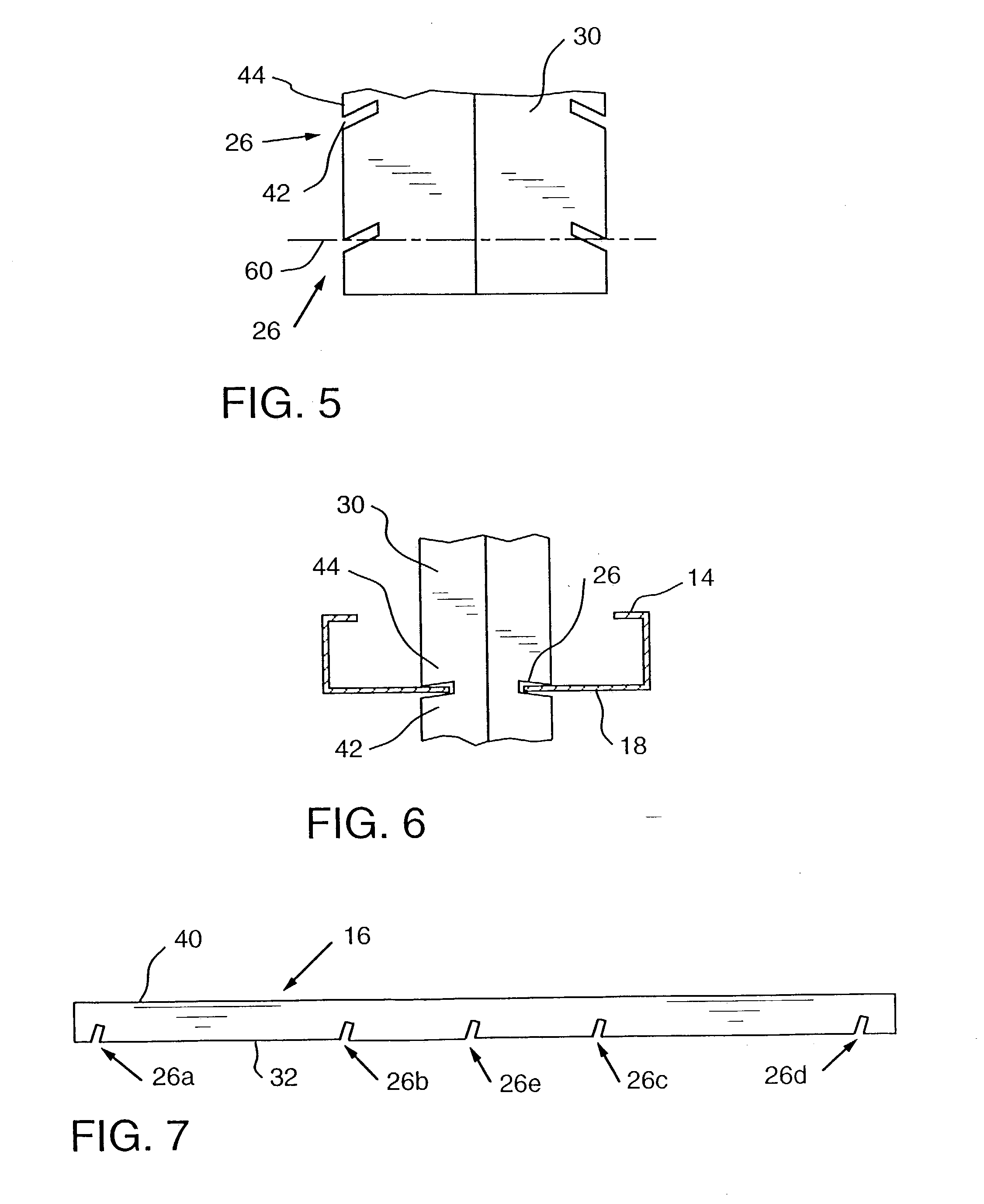
[0020] Another embodiment of the invention comprises a metal stud wall including the stud bridging / spacing member and a method of assembling a metal stud wall using the stud bridging / spacing member. The angled slots, or more accurately the angled sides thereof, coact with the webs of the studs and may inhibit twisting, turning or bowing of the studs when subjected to axial and / or lateral and / or transverse loads. Moreover, as the loads increase, the angled slots can more tightly lock with the stud webs by providing the "shear" connecting between the bridging / spacing member and the webs of the studs.
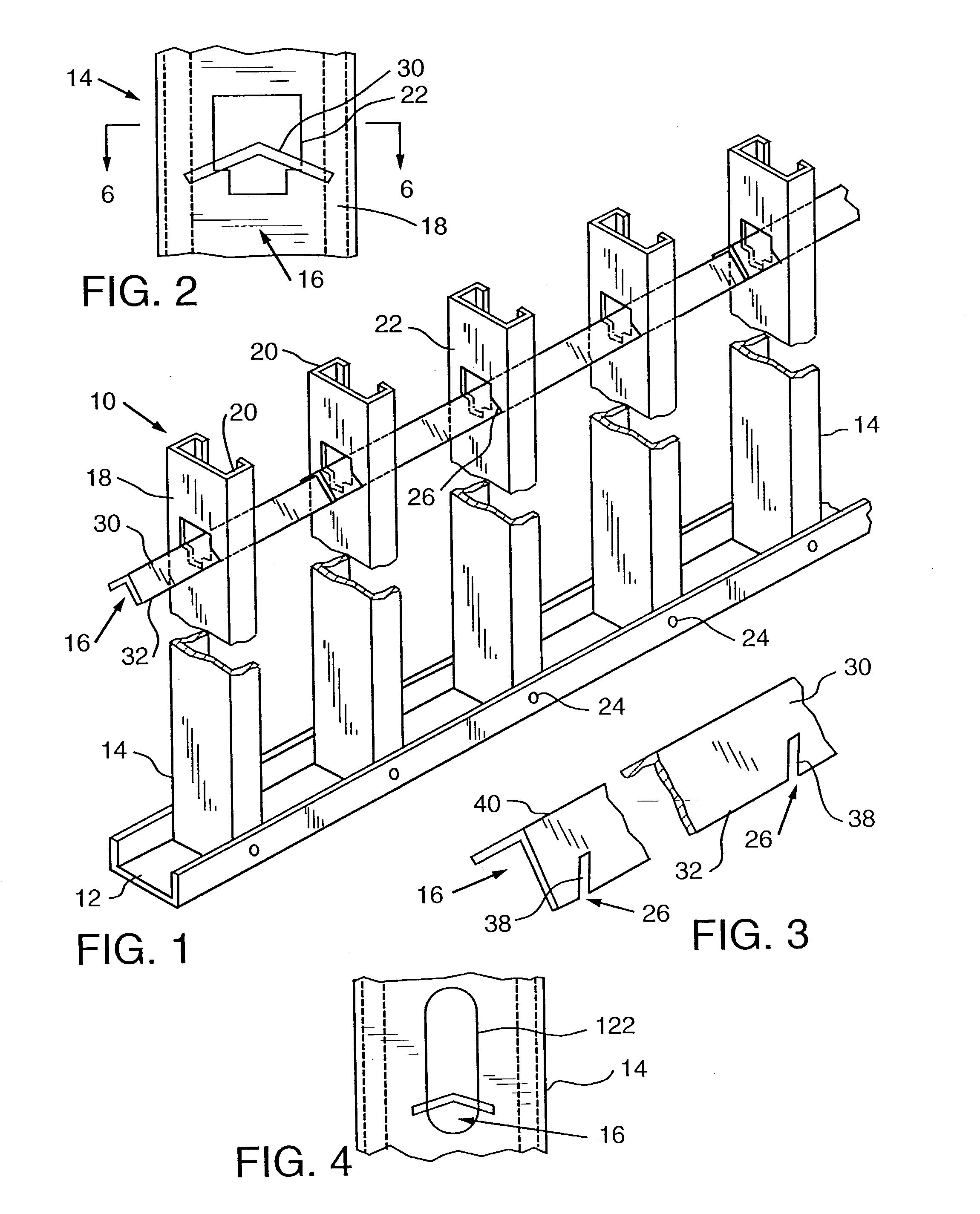
[0024] Further in accordance with an embodiment of the present invention, the elongate member has a V-shape lateral cross-section formed by longitudinally extending planar first and second portions joined at respective longitudinal edges to form the sides and vertex of the V-shape. The elongate member further may include a pair of wing portions extending laterally outwardly from respective distal ends of the V-shape elongate member. The wing portions may extend in opposite directions from the V-shape elongate member, and each wing portion may extend a distance which is approximately one-third the width of the widest part of the V-shape elongate member. The angle of the V is of least about 90.degree., more preferably at least about 120.degree. and most preferably about 130.degree.. A shallow angle increases the transverse stiffness of the elongate member, although other means may be used for this purpose.

Problems solved by technology

These loads may cause flexing (including bowing, twisting or other deformation of the stud) or turning of the metal studs which may cause the walls to crack or otherwise be flawed or damaged.
In load bearing walls, this problem is structural as well as aesthetic.
The installation of metal stud wall systems, including the reinforcing bridging systems, heretofore has been a time consuming process.
Because of the time consuming nature of the installation process, fasteners can be missed or forgotten.
In the welded channel bridging systems, welders and their equipment are relatively expensive, and welds also can be missed, or can be improperly formed.
Defects in welds can be particularly difficult to detect.
In certain situations, the bridging member may not fit tightly with the web of a stud and inadvertently come loose.
In addition, there are certain circumstances that do not occur as often in a stud wall, but which present unusual problems for a mass-produced bridging member.
For example, at a door jamb, where the studs generally are doubled up, typical mass-produced bridging members are not readily attachable to both of the studs.
Another situation that occurs is an irregular stud spacing that does not readily accommodate and / or further complicates the installation of a bridging member.

Method used


Image

  • Support apparatuses and jambs for windows and doors and methods of constructing same
  • Support apparatuses and jambs for windows and doors and methods of constructing same
  • Support apparatuses and jambs for windows and doors and methods of constructing same

Examples


Embodiment Construction

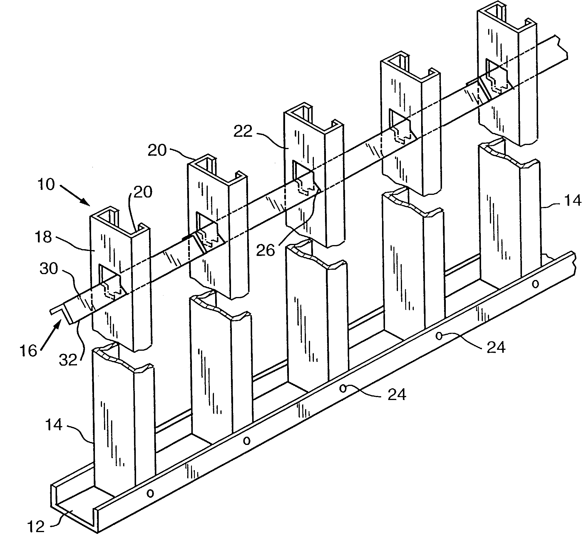
[0057] FIG. 1 illustrates the skeleton of a metal stud wall 10 according to one embodiment of the present invention. In this embodiment, the metal stud wall 10 generally comprises a base track 12, a plurality of metal studs 14 disposed in a row, at least one bridging / spacing member 16, and wall panels (not shown). The wall panels, such as wall board, may be secured in a well known manner to one or both sides of the metal studs to close the wall and to form the exterior surface or surfaces of the wall. Alternatively, one or both sides of the metal studs may be faced with masonry, such as a brick wall facing on an exterior side of a curtain wall.

[0058] The studs 14, as illustrated in FIG. 1, are generally C-shaped, as is conventional. The studs 14 have a web 18 and a pair of L-shape flanges 20 perpendicular to the web 18. There is also one or more openings 22 in the web 18. The openings 22 heretofore have been provided in metal studs to permit bridging members, electrical conduit and / ...


PUM


Abstract

A support structure such as, for example, a door jamb and a window jamb. In one embodiment, the jamb is formed from a first stud that has a web and two first flanges and a second stud with a second web and second flanges. The first stud has at least one first hole through the first web and the second stud has at least one second hole through the second web. The first and second studs are oriented such that at least one first hole is aligned with at least one second hole and a stud engager is inserted through the aligned holes to retain the studs in abutting contact to form the jamb.

Description

[0001] This non-provisional application for patent is a divisional patent application of U.S. patent application Ser. No. 09 / 888,897, filed Jun. 25, 2001 which claims priority from U.S. Provisional Patent Application Serial No. 60 / 229,583, Filed Aug. 31, 2000.FEDERALLY SPONSORED RESEARCH[0002] Not applicable.[0003] 1. Field of the Invention[0004] The invention herein described relates generally to stud wall systems and more particularly to a device for spacing and bridging studs in a stud wall, and connecting devices for use with spacing and bridging members.[0005] 2. Description of the Invention Background[0006] Metal studs are used to form walls in building structures today, including load bearing walls such as exterior walls and curtain walls. In a typical installation, the metal studs are secured by screws at their lower ends to a bottom track secured to a floor, and extend at their upper ends into a top track secured to overhead joists which may form the framework for an upper ...

Claims


Application Information

Patent Timeline
Patent Type & Authority Applications(United States)
IPC IPC(8): E04B2/58E04B2/74E04B2/76
CPCE04B2/58E04B2/7457Y10T403/7073Y10T428/1241E04B2/763
Inventor ELDERSON, WILLIAM L.
Owner CLARKWESTERN DIETRICH BUILDING SYST
Why Eureka
Try Eureka