Mobile speedometer system, and associated methods

a speedometer and mobile technology, applied in the field of mobile speedometer systems, can solve the problems of not being able to quantitatively compare the roughness of the journey of the user, the only qualitative effect of the activity, and the inability to quantitatively determine the speed of the user, etc., to achieve the effect of reliable determination of speed

Inactive Publication Date: 2003-05-15
NIKE INC
View PDF31 Cites 142 Cited by
  • Summary
  • Abstract
  • Description
  • Claims
  • Application Information

AI Technical Summary

Benefits of technology

[0011] It is yet another object of the invention to provide improvements to sporting vehicles which are ridden by sporting participants, and which provide a determination of speed, airtime, drop distance and / or power of the vehicle.
[0120] In areas where the ski run is visible, the speed and trajectory of a skier may be achieved by the use of a digital imaging system, in accord with another aspect. The imaging system can thus include a CCD camera that looks at the slope and watches skiers traverse down the slope. By knowing the distances along the slope, and the fact that the camera is stationary, the distance moved is determined frame to frame, corresponding to position in time that correlates to speed. Skiers can be identified by signs they wear, including a distinctive pattern which allows identification of individual skiers.

Problems solved by technology

However, persons in such sporting activities only have a qualitative sense as to speed and loft or "air" time.
Speed or velocity also remain unquantified.
Currently, they cannot quantitatively compare how rough their journeys were relative to one another.

Method used


Image

  • Mobile speedometer system, and associated methods
  • Mobile speedometer system, and associated methods
  • Mobile speedometer system, and associated methods

Examples


Embodiment Construction

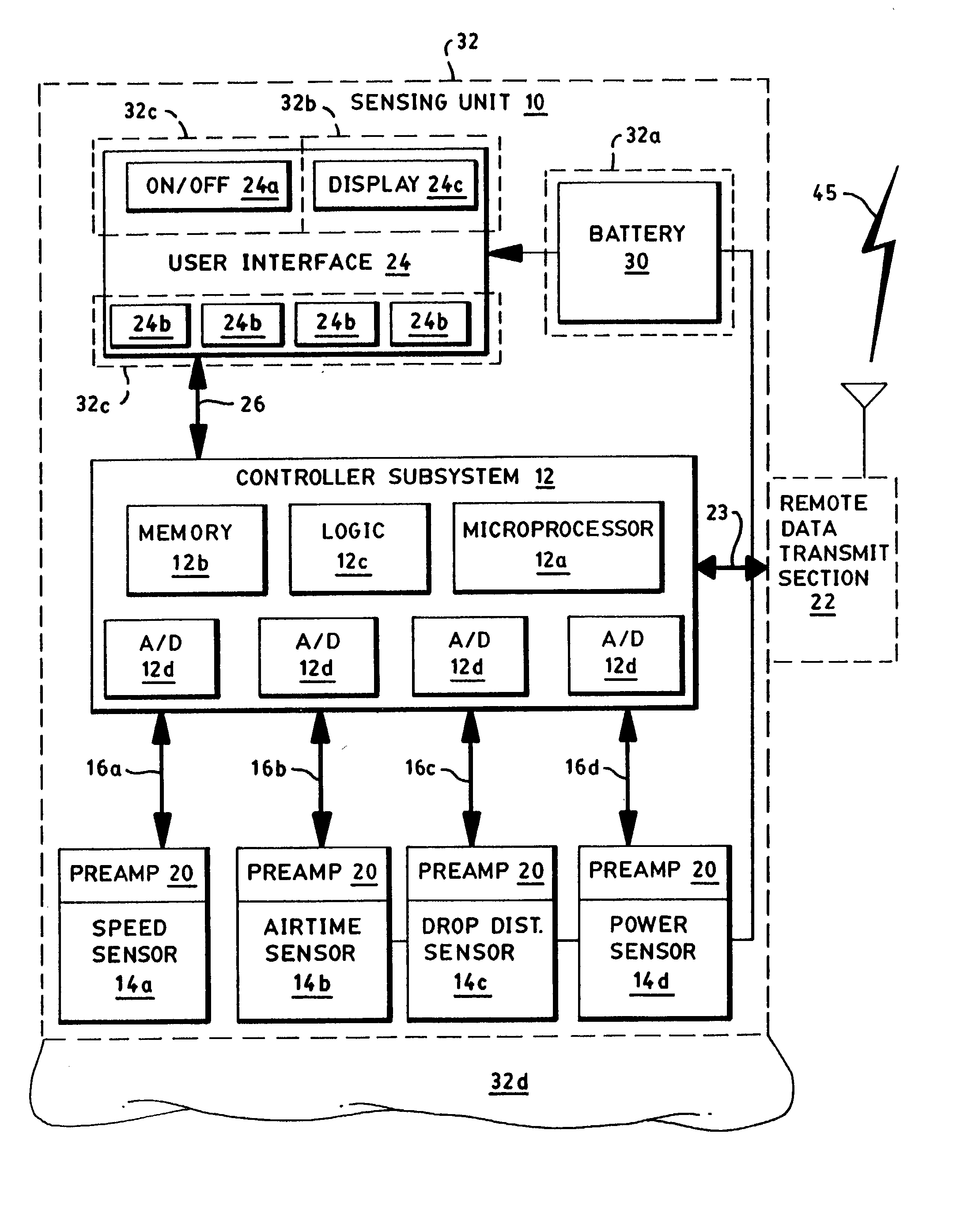
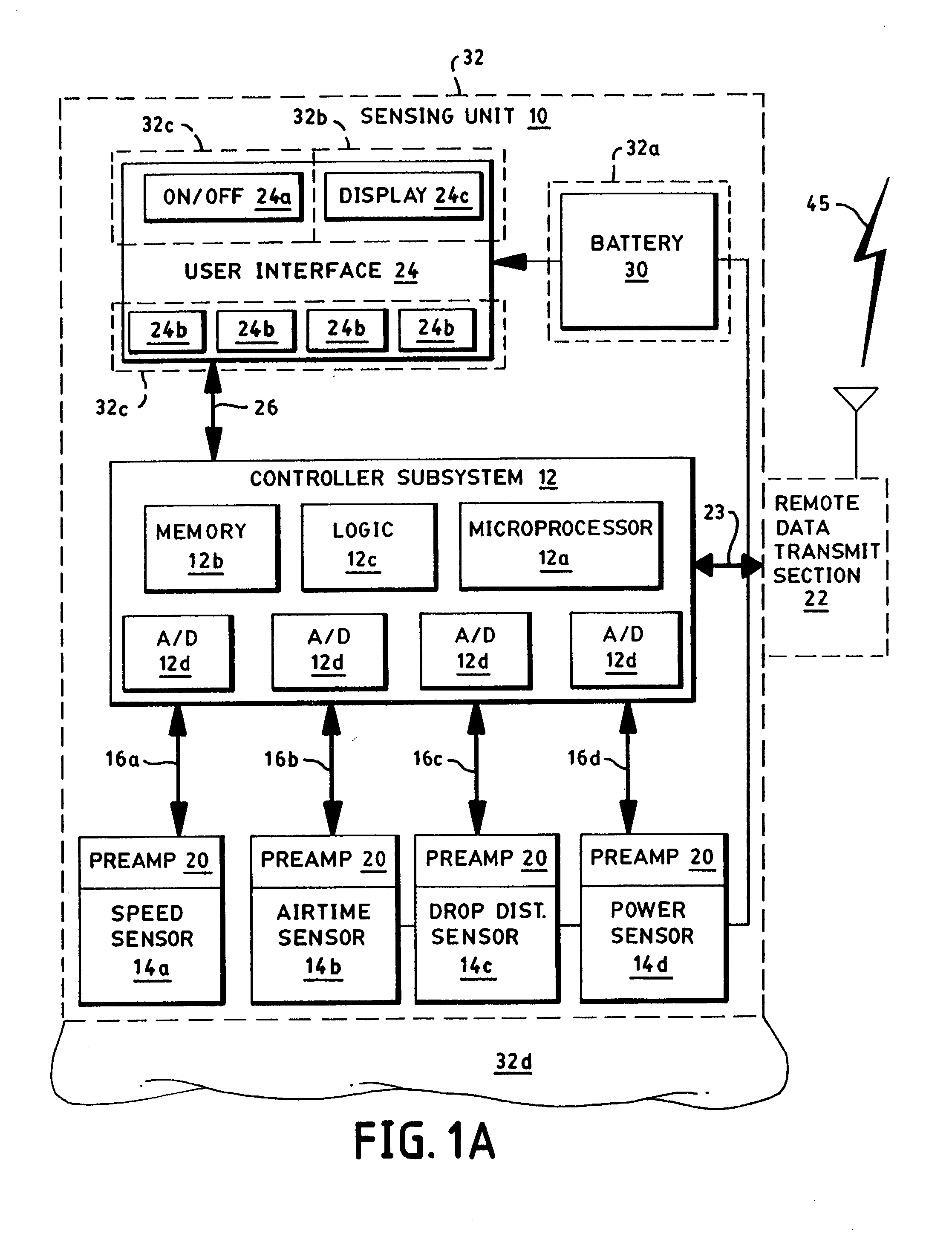
[0176] FIG. 1A illustrates a sensing unit 10 constructed according to the invention. A controller subsystem 12 controls the unit 10 and is connected to one or more sensors 14a-14d. Typically, the subsystem 12 receives data from the sensors 14a-d through data line 16a-d; though certain sensors 14 require or permit control signals, so data lines 16a-d are preferably bi-directional. It is not necessary that the unit 10 incorporate all sensors 14a-14d and only one of the sensors 14a, 14b, 14c or 14d is required so as to provide performance data. In one preferred embodiment, however, the unit 10 includes all four sensors 14a-14d. In another preferred embodiment, only the airtime sensor 14b is included within the unit 10.

[0177] The sensors 14a-14d take a variety of forms, as discussed herein. Generally, the speed sensor 14a provides data indicative of speed to the controller subsystem 12 along data line 16a. One exemplary speed sensor 14a utilizes a microwave Doppler module such as made b...


PUM


Abstract

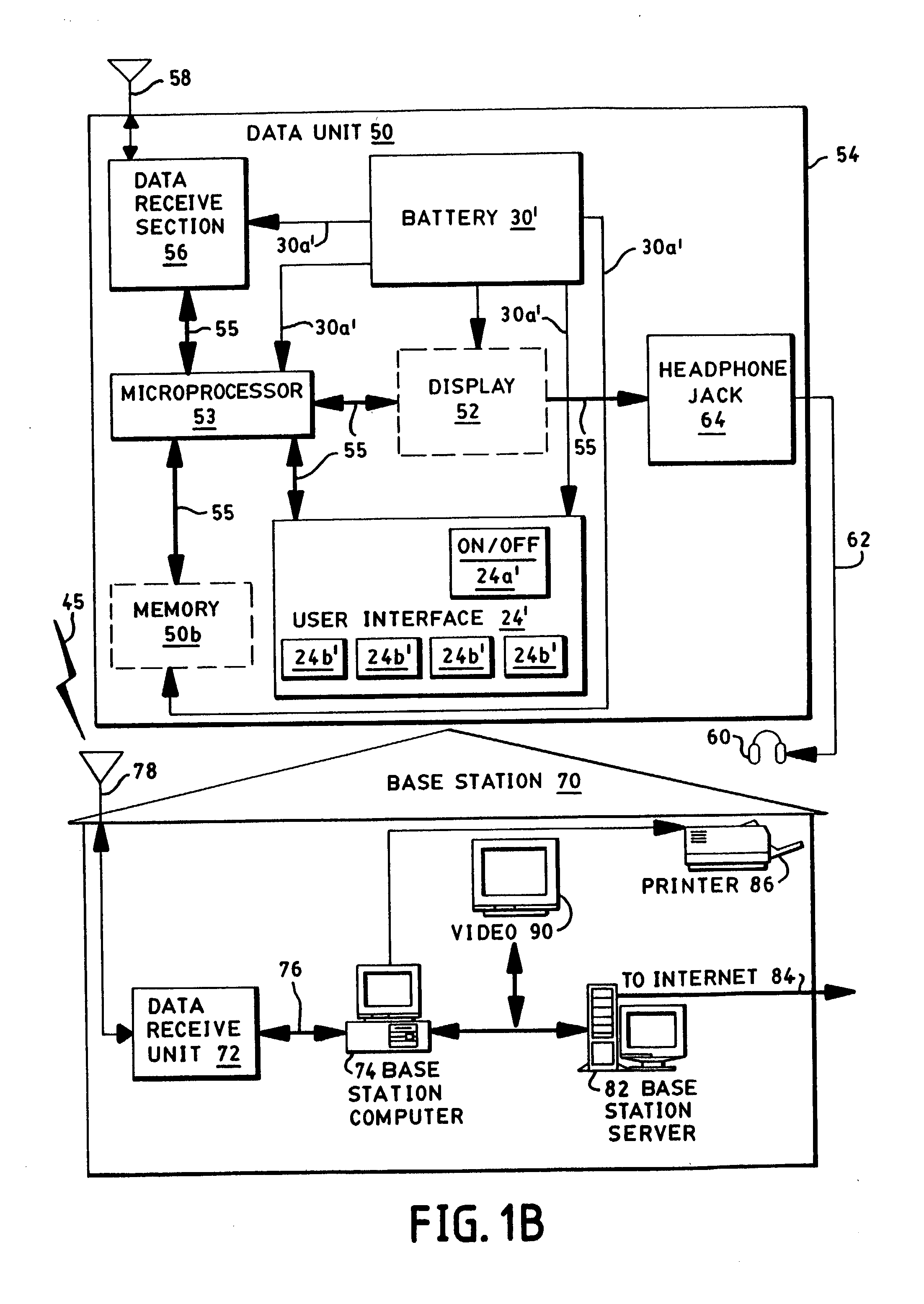
The invention detects the loft time, speed, power and / or drop distance of a vehicle, such as a sporting vehicle, during activities of moving and jumping. A loft sensor detects when the vehicle leaves the ground and when the vehicle returns to the ground. A controller subsystem converts the sensed information to determine a loft time. A display shows the recorded loft time to a user of the system. In addition, a speed sensor can detect the vehicle's speed for selective display to the user. A power sensing section informs the user of expended energy, which can be compared to other users. A drop distance sensing unit informs the user of the peak height of a jump, during an airtime. Gaming on the internet is facilitated to connect worldwide sport enthusiasts.

Description

[0001] This application is a continuation of and claims priority to U.S. patent application Ser. No. 09 / 089,232, filed Jun. 2, 1998, which is a continuation-in-part of U.S. application Ser. No. 08 / 764,758 (now U.S. Pat. No. 5,960,380), filed on Dec. 12, 1996, and U.S. application Ser. No. 08 / 867,083, filed on Jun. 2, 1997, and which claims priority to U.S. Provisional Application No. 60 / 077,251, filed on Mar. 9, 1998, each of which is expressly incorporated herein by reference.[0002] The invention relates generally to monitoring and quantifying sport movement (associated either with the person or with the vehicle used or ridden by the person), including the specific parameters of "air" time, power, speed, and drop distance. The invention also has "gaming" aspects for connecting users across the Internet. The invention is particularly useful in sporting activities such as skiing, snowboarding, mountain biking, wind-surfing, skate-boarding, roller-blading, kayaking, racing, and runnin...

Claims


Application Information

Patent Timeline
Patent Type & Authority Applications(United States)
IPC IPC(8): A63B69/18A63B71/06G01P3/42G01P3/50G01P5/24G01S11/14G01S15/60G04F8/08G04F10/00G06F15/00
CPCA42B3/0433G01P1/16A61B2562/0219A63B5/00A63B24/0062A63B69/0093A63B69/16A63B69/18A63B69/182A63B71/06A63B71/0605A63B71/10A63B2024/0071A63B2069/185A63B2071/065A63B2220/12A63B2220/13A63B2220/14A63B2220/16A63B2220/30A63B2220/40A63B2220/44A63B2220/62A63B2220/64A63B2220/801A63B2220/808A63B2220/833A63B2244/19A63C5/06A63C2203/18G01C21/10G01C21/20G01P3/42G01P3/50G01P15/00G01P15/0891G01S11/14G01S15/60G01S19/19G04F8/08A61B5/6895A61B5/6804A61B5/6807G01P1/08A61B5/11
Inventor VOCK, CURTIS A.DARCY, DENNISBURKE, SHAWNFLENTOV, PETER
Owner NIKE INC
Why Eureka
Try Eureka