Grammar for message passing in a distributed simulation environment

Inactive Publication Date: 2003-05-15
SUN MICROSYSTEMS INC
View PDF46 Cites 14 Cited by
  • Summary
  • Abstract
  • Description
  • Claims
  • Application Information

AI Technical Summary

Problems solved by technology

However, as the electronic systems (and the components forming systems) have grown larger and more complex, single-syst

Method used


Image

  • Grammar for message passing in a distributed simulation environment
  • Grammar for message passing in a distributed simulation environment
  • Grammar for message passing in a distributed simulation environment

Examples


Embodiment Construction

[0033] Distributed Simulation System Overview

[0034] In the discussion below, both the computer systems comprising the distributed simulation system (that is, the computer systems on which the simulation is being executed) and the electronic system being simulated are referred to. Generally, the electronic system being simulated will be referred to as the "system under test".

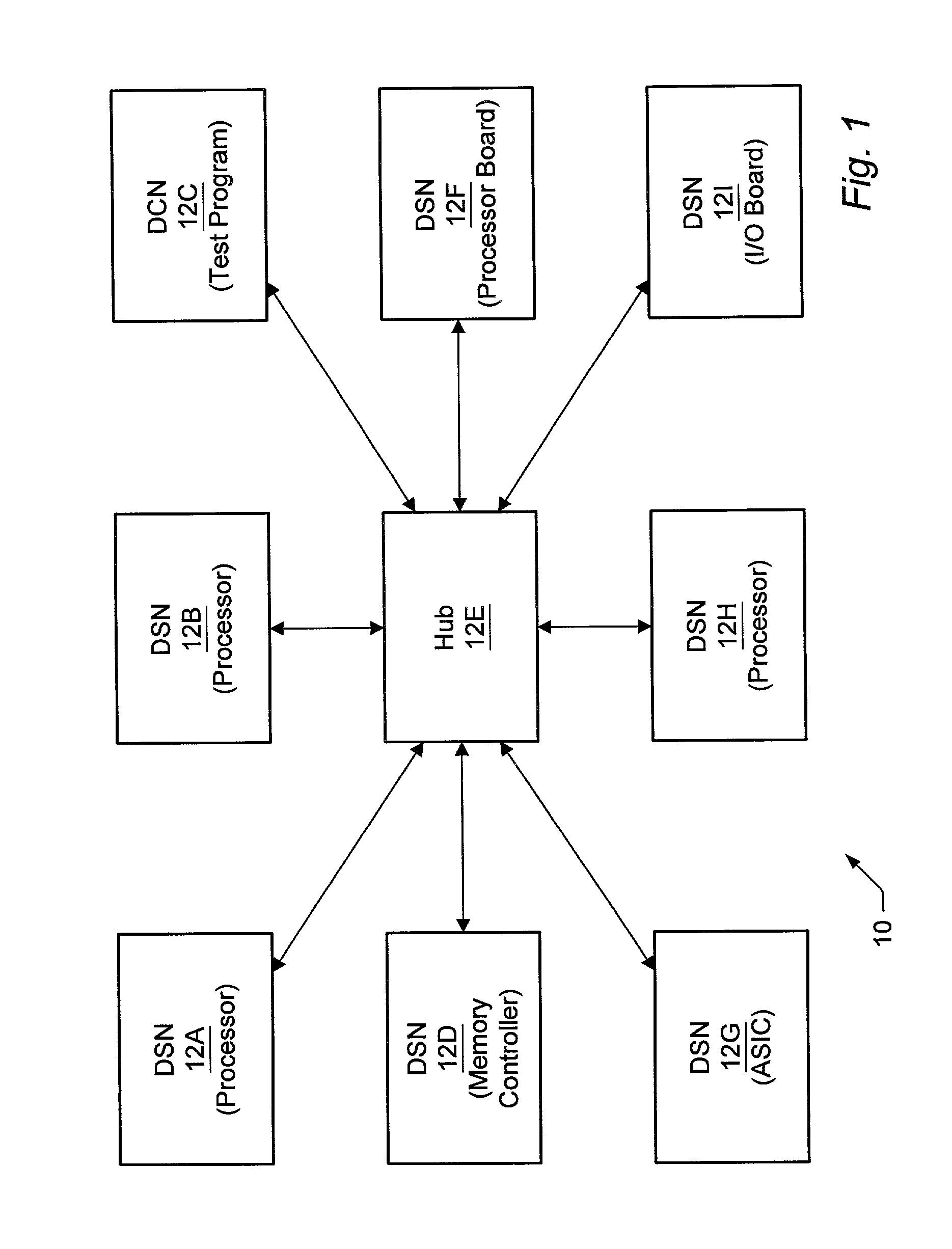
[0035] Turning now to FIG. 1, a block diagram of one embodiment of a distributed simulation system 10 is shown. Other embodiments are possible and contemplated. In the embodiment of FIG. 1, the system 10 includes a plurality of nodes 12A-12I. Each node 12A-12D and 12F-12I is coupled to communicate with at least node 12E (which is the hub of the distributed simulation system). Nodes 12A-12B, 12D, and 12F-121 are distributed simulation nodes (DSNs), while node 12C is a distributed control node (DCN).

[0036] Generally, a node is the hardware and software resources for: (i) simulating a component of the system under t...


PUM


Abstract

A distributed simulation system includes a plurality of nodes and a hub. Each node may simulate a portion of a system under test, or may execute a test program for the simulation. The hub may route message packets from one node to another. The message packets are formatted according to a grammar used by the distributed simulation system, which abstracts the physical signals of the system under test to logical ports. Additionally, some embodiments may include other commands, such as commands for configuring the distributed simulation system, describing the logical ports and logical signals within the logical ports, and mapping the logical signals to physical signals. A formatter program may be used in each node and the hub to format message packets for transmission, according to the grammar. A parser program may be used in each node and the hub to parse received message packets, again according to the grammar.

Description

[0001] 1. Field of the Invention[0002] This invention is related to the field of distributed simulation systems and, more particularly, to communication between nodes in a distributed simulation system.[0003] 2. Description of the Related Art[0004] Generally, the development of components for an electronic system such as a computer system includes simulation of models of the components. In the simulation, the specified functions of each component may be tested and, when incorrect operation (a bug) is detected, the model of the component may be changed to generate correct operation. Once simulation testing is complete, the model may be fabricated to produce the corresponding component. Since many of the bugs may have been detected in simulation, the component may be more likely to operate as specified and the number of revisions to hardware may be reduced. The models are frequently described in a hardware description language (HDL) such as Verilog, VHDL, etc. The HDL model may be sim...

Claims


Application Information

Patent Timeline
IPC IPC(8): H04L12/24H04L12/26H04L12/56H04L29/08
CPCH04L43/50H04L67/125H04L69/329H04L67/10H04L67/12
Inventor FREYENSEE, JAMES P.FRANKEL, CARL B.SIVIER, STEVEN A.CAVANAGH, CARL
Owner SUN MICROSYSTEMS INC
Why Eureka
Try Eureka