Diagnostic method and system

a technology of applied in the field of computer-aided diagnostic method and system, can solve the problems of diagnostic error, no assurance that the appropriate part of the system will be replaced, and the accuracy of the diagnostic results is not guaranteed, so as to achieve easy integration in the data, field experience, and easy to understand

Inactive Publication Date: 2006-07-06
IBM CORP
View PDF8 Cites 38 Cited by
  • Summary
  • Abstract
  • Description
  • Claims
  • Application Information

AI Technical Summary

Benefits of technology

[0019] Another advantage of the present invention is to provide a method that is predictable, in the sense that it will either converge to the identification of a failure or the conclusion that the failure is not known to the system. The method will not try to perform an educated guess.
[0020] One other advantage of the method is that the authoring effort to fill data in the diagnostic method database is medium for a first system and low for the following systems.
[0021] One other advantage of the method is that the methods of the prior art require end-to-end vehicle experts and even with mathematical understanding (with MBR methods), whereas the method of the present invention only requires vehicle experts, domain users and technical advisor because the system is easy to understand, the decomposition being “natural”.
[0022] One other advantage with the method of the present invention is that the field experience can be easily integrated in the data. It can be done automatically via the weights and manua...

Problems solved by technology

With this method, except if the technician is particularly expert in a given system, there is no insurance that the appropriate part of the system will be replaced.
However, the drawback is that the result is approximate and could be very far from the exact result if the failure problem has not been modeled.
This can lead to an error of diagnostic which is not reported as is.
The second problem with this method is that the model changes with time and the model accuracy after a while is very difficult to evaluate.
In order to be operational, with MBR, every object ...

Method used


Image

  • Diagnostic method and system
  • Diagnostic method and system
  • Diagnostic method and system

Examples


Embodiment Construction

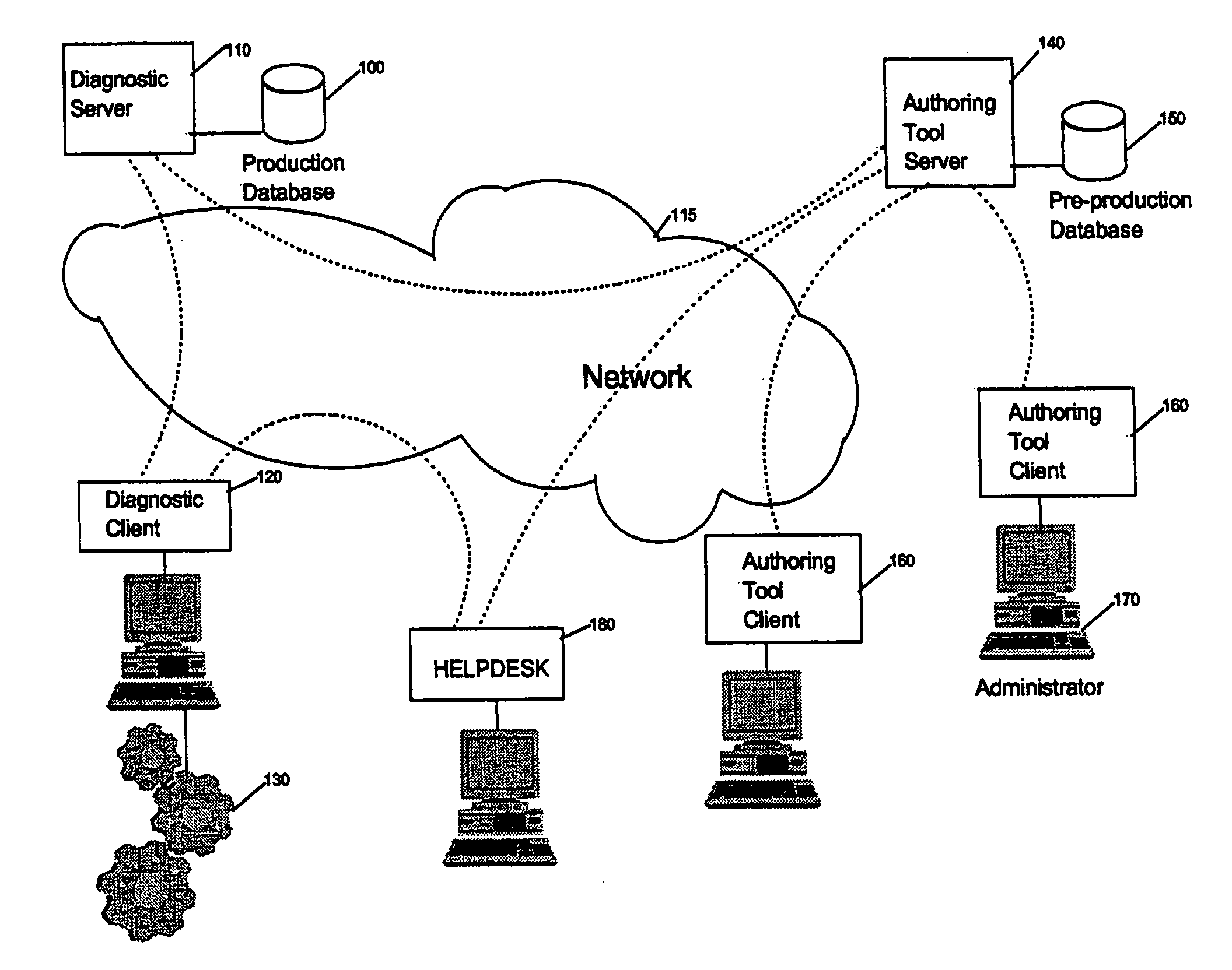
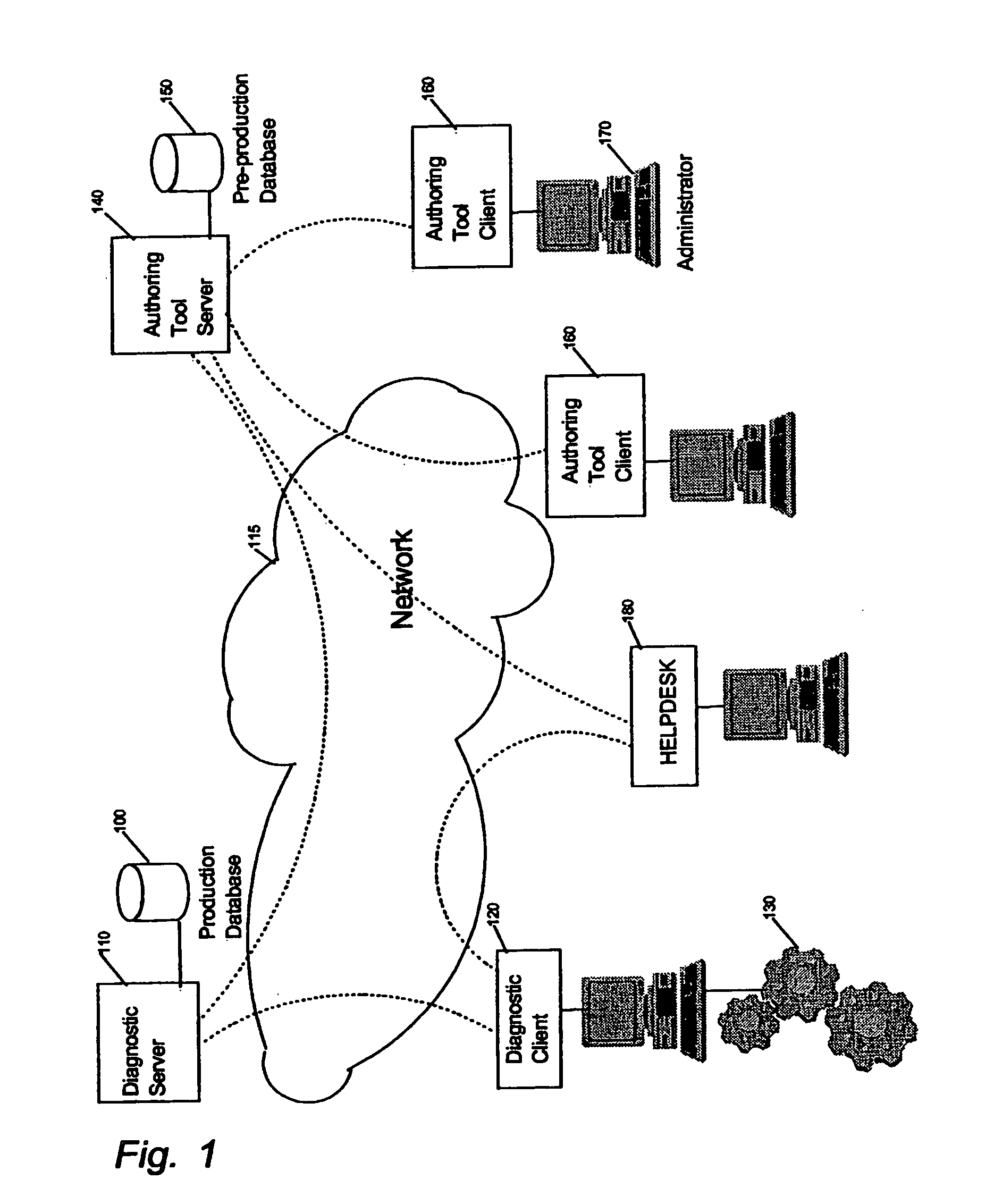
[0040]FIG. 1 illustrates the environment of the method of the invention according to the preferred embodiment which allows, starting from the symptoms of a problem, to identify the smallest replaceable or repairable unit in an automated system (130), such as a car which includes testable components, some of them being uniquely testable through a controller of the system. If the system is a car, the car is usually located in a garage and the technician has a workstation operating the client side (120) of a client server diagnostic application. The workstation is connected to the diagnostic server (110) through a network (115) which can be an Internet network. Through a dialog, the technician is guided to test or set elements of the system in a status which allows the diagnostic server to obtain the right information and reach a conclusion on the solution. The diagnostic server uses a production database (100) for diagnostic data. This database (100) is a shadow of the last operationa...


PUM


Abstract

A method and system comprising a diagnostic symptom tree system for diagnosing a failing system element causing a symptom in a system-under-test. A diagnostic symptom tree comprises symptom roots and dependent lower function nodes and sub-function nodes. Element nodes depend from the function or sub-function nodes, and a plurality of penultimate failure mode leaves depend from the element nodes. The function and sub-function nodes and the failure mode leaves comprise test information. Responsive to positive test results, the diagnostic symptom tree is configured to identify a function or sub-function or element node associated to a lowest symptom tree node or failure mode leaf for which a test is positive, or advise that no failing function or sub-function or element is found. In one aspect of the invention, nodes may include parameter values allowing successive selections of the nodes of the symptom tree for test iterations according to the parameter values.

Description

FIELD OF THE INVENTION [0001] The present invention generally relates to computer aided diagnostic methods and systems applied to systems to be diagnosed, able or not to collect information from internal elements and / or to exchange information with the computer. BACKGROUND OF THE INVENTION [0002] Computer aided diagnostic methods are more and more used with the extensive integration of electronic and electrical equipment, for instance into motorcars to control engines, braking systems and other on-board systems. For example, the multiplexing technology, used by car manufacturers and suppliers, replaces the numerous hard-wired electrical connections between components by buses. These buses allows for transmission of individual or broadcast messages to and from all components. [0003] The first intent of a diagnostic method is to determine the failure and the action to be accomplished to repair it. The more complex the system for which a diagnostic is required, the more the diagnostic ...

Claims


Application Information

Patent Timeline
IPC IPC(8): G06F11/00
CPCG05B23/0248G05B23/0278G06F11/2257
Inventor COUSIN, BENOITNEYT, JEAN-LOIS
Owner IBM CORP
Why Eureka
Try Eureka