Data copy method

a data copy and data technology, applied in the direction of input/output to record carriers, redundancy hardware error correction, instruments, etc., can solve the problem that no prior art has indicated in regards to methods for enhancing the processing capacity of logic storage apparatus

Inactive Publication Date: 2003-05-29
HITACHI LTD
View PDF8 Cites 45 Cited by
  • Summary
  • Abstract
  • Description
  • Claims
  • Application Information

AI Technical Summary

Problems solved by technology

However, no prior art has indicated in regards to methods for enhancing the processing capacity of the logic storage apparatus at the data copying source.

Method used


Image

  • Data copy method
  • Data copy method
  • Data copy method

Examples


Embodiment Construction

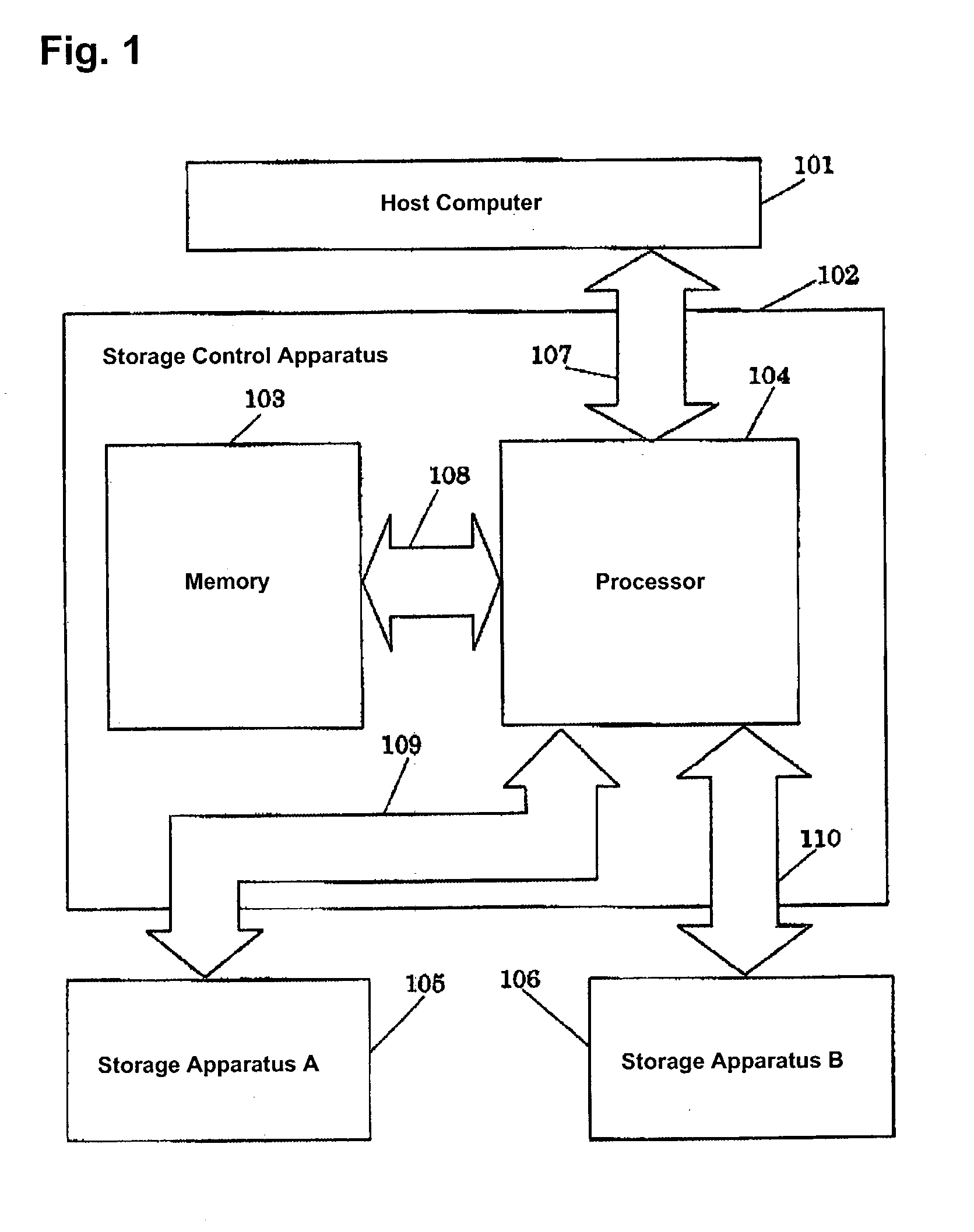
[0044] FIG. 1 shows a system configuration of the present embodiment. A storage control apparatus 102 consists of a memory 103 used as a buffer to temporarily store data from a host computer 101 and data from a storage apparatus A 105 and a storage apparatus B 106, a processor 104 that controls the data transfer between the host computer 101 and the storage apparatuses A 105 and B 106, a transfer path 107 that connects the host computer 101 with the processor 104, a transfer path 108 that connects the memory 103 with the processor 104, a transfer path 109 that connects the memory apparatus A 105 with the processor 104, and a transfer path 110 that connects the memory apparatus B 106 with the processor 104. In addition to functioning as a buffer, the memory 103 records control information of the control apparatus 102.

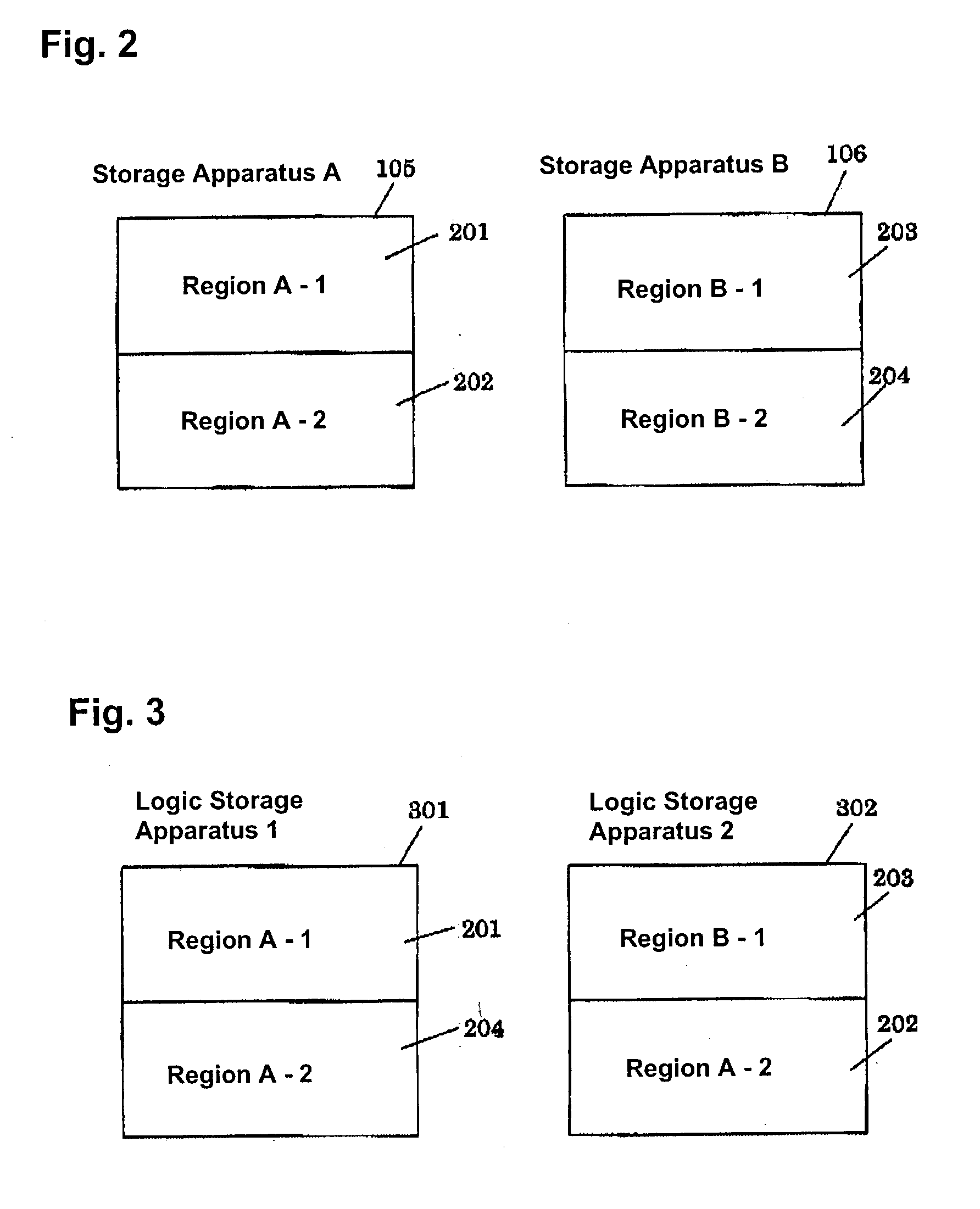
[0045] FIG. 6 shows a table 601 indicating which of the region 1 and region 2 of the storage apparatus make up a region 1 and a region 2 of each of the logic storage app...


PUM


Abstract

A data copy method for a disk sub system that is equipped with a first storage apparatus including a first logic storage apparatus divided into a first region and a second region and a second storage apparatus including a second logic storage apparatus divided into a first region and a second region, the first logic storage apparatus and the second logic storage apparatus connecting to a host apparatus, wherein data on the first logic storage apparatus is copied to the second logic storage apparatus by an instruction from the host apparatus. With the data copy method, the second logic storage apparatus is designated as a copy destination for copying data of the first logic storage apparatus, the second region of the first logic storage apparatus and the second region of the second logic storage apparatus are switched with one another, and data stored in the first region and the second region within the first storage apparatus are copied to the first region and the second region within the second storage apparatus.

Description

[0001] The present invention relates to a storage system consisting of a plurality of logic storage apparatuses, and more particularly to a method and system of creating pairs and copies of logic storage apparatuses within the same control apparatus.DESCRIPTION OF RELATED ART[0002] Pairing and copying operations of logic storage apparatuses may be performed within the same control apparatus. In this type of apparatus, data copying can be completed even though the frequency of data copying processes is reduced, in contrast to data renewal and reference processes performed upon requests from a host computer. Because of this, the access frequency of the logic storage apparatus at the destination of the copy is held to a lower level than that of the logic storage apparatus at the copying source. Conversely, it is desirable that the processing capacity of the logic storage apparatus at the source of data copying would be high. However, no prior art has indicated in regards to methods for...

Claims


Application Information

Patent Timeline
Patent Type & Authority Applications(United States)
IPC IPC(8): G06F3/06G06F11/20G06F12/00
CPCG06F11/2087G06F11/2082
Inventor KAGA, TAKASHIARAI, KOUJIWATANABE, HARUAKI
Owner HITACHI LTD
Why Eureka
Try Eureka