Arrangement for the detection for relative movements or relative position of two objects

a technology of relative movement and arrangement, applied in the direction of force/torque/work measurement apparatus, instrumentation, force components, etc., can solve the problem of requiring a relatively large area for arrangemen

Inactive Publication Date: 2003-06-05
SOC CIV GALILEO 2011
View PDF8 Cites 30 Cited by
  • Summary
  • Abstract
  • Description
  • Claims
  • Application Information

AI Technical Summary

Problems solved by technology

It is, however, disadvantageous that the arrangement requires a relatively large area.

Method used


Image

  • Arrangement for the detection for relative movements or relative position of two objects
  • Arrangement for the detection for relative movements or relative position of two objects
  • Arrangement for the detection for relative movements or relative position of two objects

Examples


Embodiment Construction

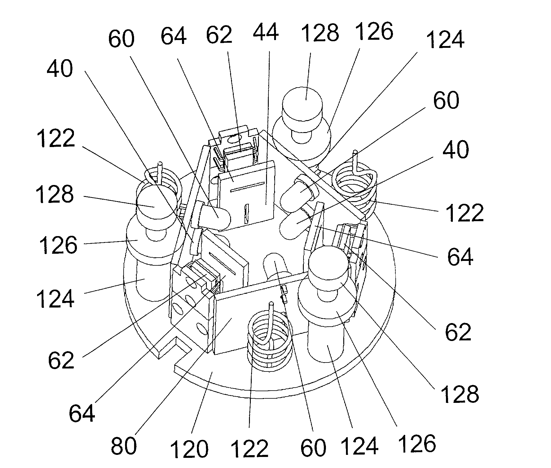
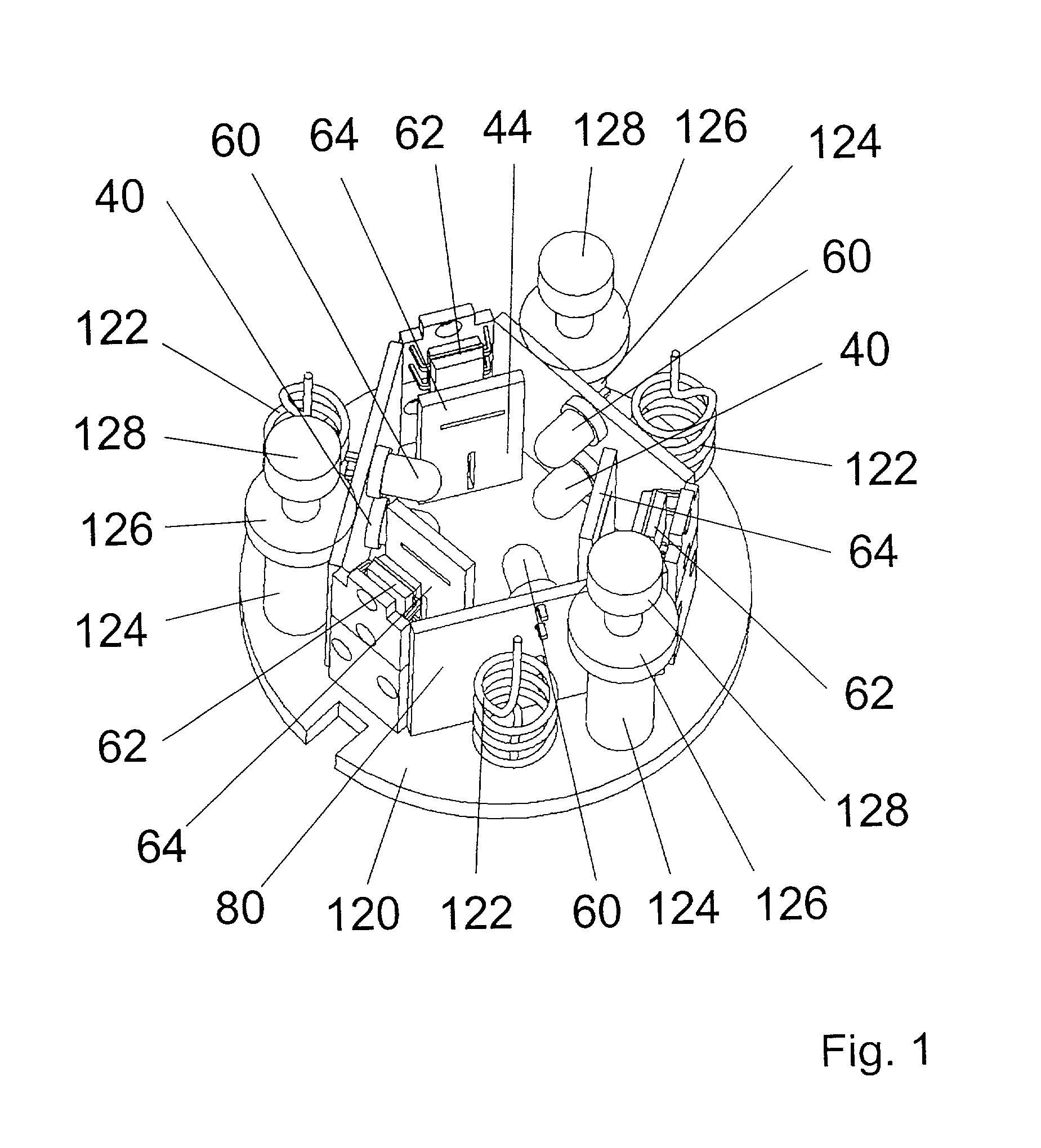
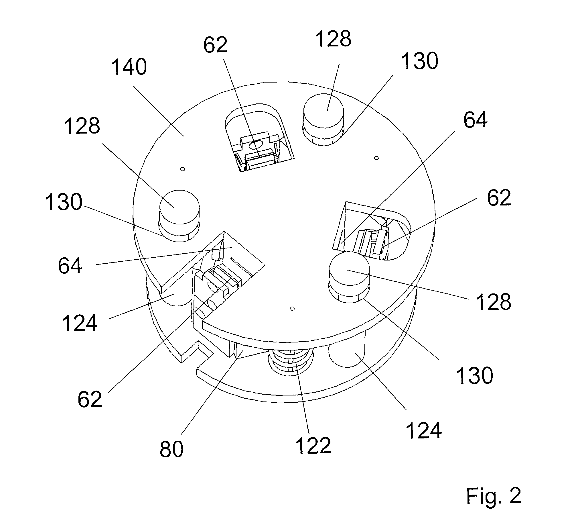
[0042] The optoelectronic arrangement for the detection of relative movements or relative positions of two objects as shown in FIG. 1 comprises twelve optoelectronic elements, namely six ILEDs 40, 60 and six position sensitive infrared detectors 42, 62, which are arranged in a first plane and a second plane different from the first plane. Six optoelectronic elements 40, 42, namely three ILEDs 40 and three position sensitive infrared detectors 42 are arranged in the first plane and six optoelectronic elements 60, 62, namely three ILEDs 60 and three position sensitive infrared detectors 62 are arranged in the second plane.

[0043] Each position sensitive infrared detector 42, 62 is illuminated by an ILED 40, 60. Thereby one ILED 40, 60 illuminates exactly one position sensitive detector 42, 62 in order to form a measuring cell. The light beam extends in the same plane in which the optoelectronic elements of the respective measuring cell are arranged.

[0044] The ILED's are mounted in pair...


PUM

PropertyMeasurementUnit
optoelectronicaaaaaaaaaa
photosensitiveaaaaaaaaaa
degrees of freedomaaaaaaaaaa

Abstract

An optoelectronic arrangement for the detection of relative movements or relative positions of two objects, with the arrangement comprising at least four optoelectronic elements, characterised in that the optoelectronic elements are arranged in at least one first plane and in a second plane different from the first one in such a manner that at least three optoelectronic elements are arranged in the first plane and at least one optoelectronic element is arranged in the second plane. Further, a force and/or moment sensor provided with this arrangement with a first board and a second board, with the first board and the second board being elastically connected with each other and movable relative to one another. Finally, a personal computer keyboard which is provided with such a force and/or moment sensor.

Description

DESCRIPTION[0001] 1. Background of the Invention[0002] The invention relates to an optoelectronic arrangement for the detection of relative movements or relative positions of two objects, with the arrangement comprising at least four optoelectronic elements. In addition, the invention relates to a force and / or moment sensor which utilises such an arrangement. Finally, the invention relates to a PC keyboard which comprises the inventive force and / or moment sensor.[0003] 2. State of the Art[0004] As arrangements for the detection of relative movements of two objects in force and / or moment sensors, arrangements with optoelectronic measuring cells have widely been accepted. The reason is the simple construction together with high precision and reliability.[0005] DE 36 11 337 A1 discloses an optoelectronic arrangement accommodated in a plastic ball which can simultaneously detect six components, i.e. displacements along three axes and angular rotations about three axes. For this purpose,...

Claims


Application Information

Patent Timeline
Patent Type & Authority Applications(United States)
IPC IPC(8): G01B11/00G01B11/03G01B11/26G01D5/34G01L5/16G06F3/02G06F3/042
CPCG01D5/34G06F3/0304G06F3/0213G01L5/166
Inventor GOMBERT, BERND
Owner SOC CIV GALILEO 2011
Why Eureka
Try Eureka