Overload protection switch

a technology for protecting switches and overloads, applied in the field of switches, can solve problems such as the inability of bi-metal plates to protect appliances from overloading, and achieve the effects of improving overload protection, speeding up the deformation of bi-metal plates, and protecting from overloading

Active Publication Date: 2006-01-31
HUANG ALBERT
View PDF10 Cites 7 Cited by
  • Summary
  • Abstract
  • Description
  • Claims
  • Application Information

AI Technical Summary

Benefits of technology

[0011]The primary objective of the present invention is to provide an improved overload protection switch having a conductor connecting the first primary leg to the second primary leg and being adjacent to the bi-metal plate so that not only will the current passing through the bi-metal plate raise the temperature of the bi-metal plate, but also the current passing through the conductor will raise the temperature of the conductor, which in return will speed up the deformation of the bi-metal plate and thus the appliance is protected from overloading.

Problems solved by technology

However, if the designated ampage to pass through the bi-metal plate is 3 A and the electrical appliance connected to the switch has an ampage tolerance lower than 3 A, the movement of the bi-metal plate will not protect the appliance from overloading.

Method used


Image

  • Overload protection switch
  • Overload protection switch
  • Overload protection switch

Examples


Embodiment Construction

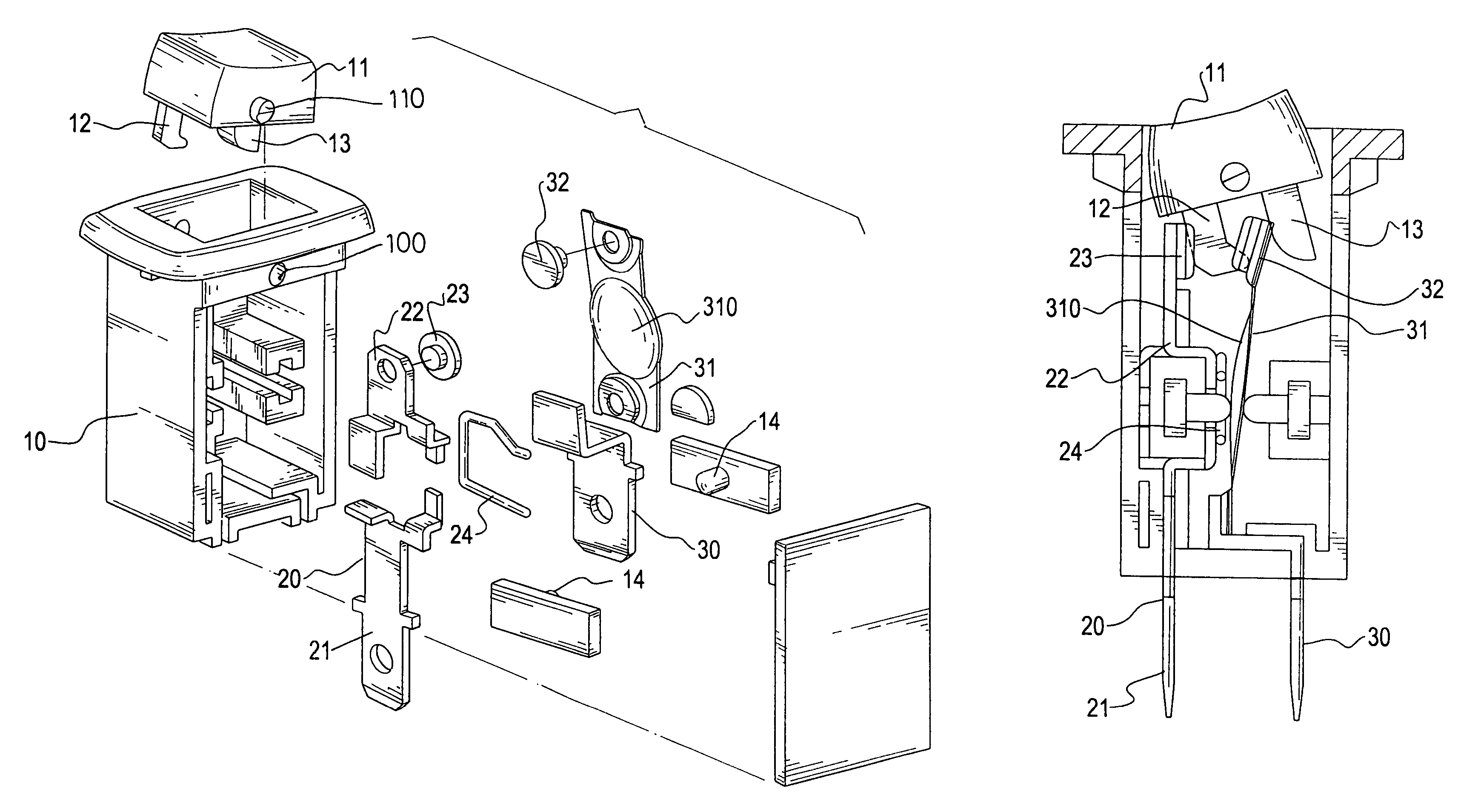
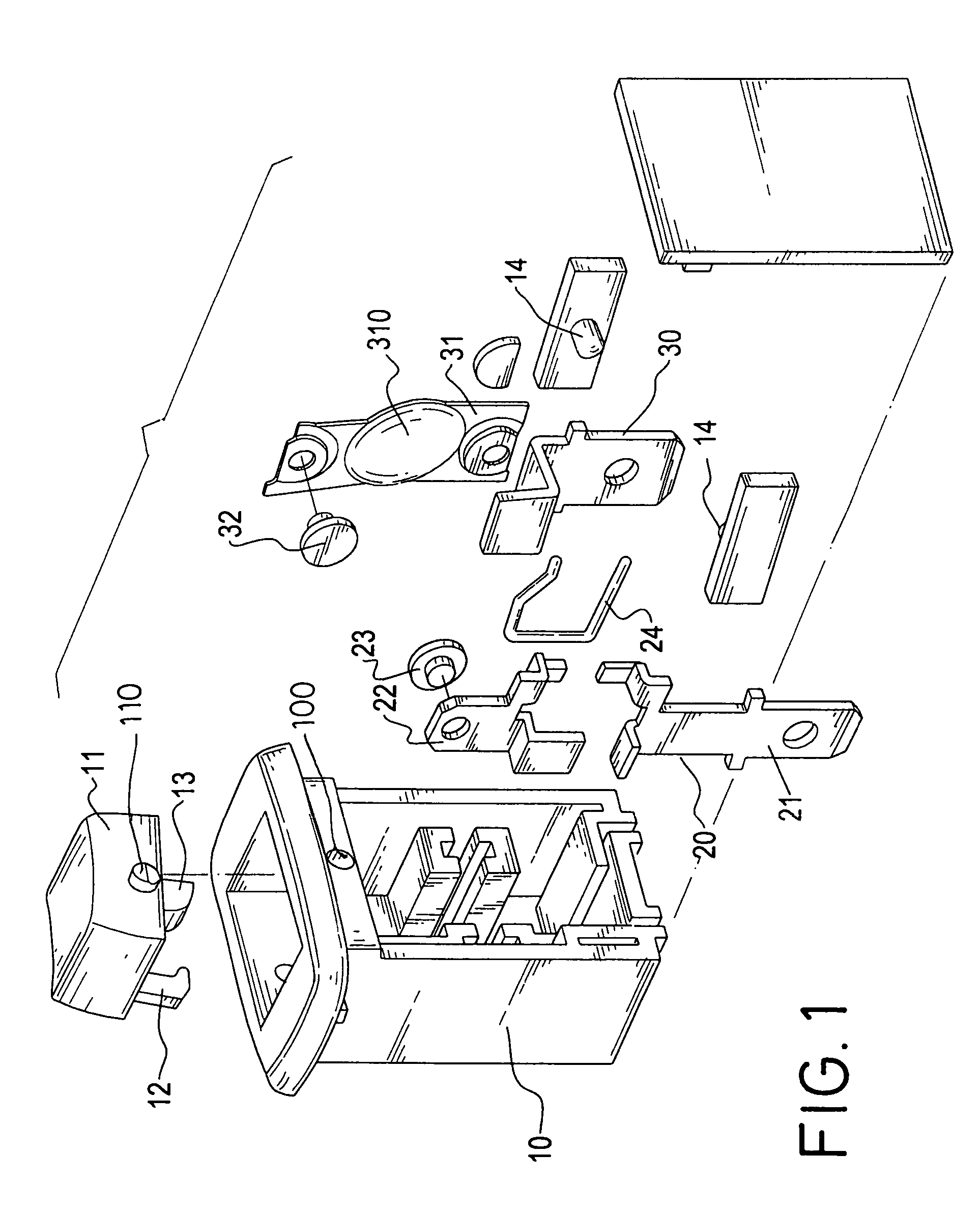
[0018]With reference to FIGS. 1 and 2, the overload protection switch in accordance with the present invention includes a hollow housing (10) with a button (11) pivotally engaged with a top portion of the housing (10), a primary leg (20), a second primary leg (30) and a bi-metal plate (31).

[0019]The housing (10) has two pivot holes (100) respectively defined in opposite sides of the upper portion of the housing (10) to correspond to two bosses (110) respectively formed on two opposite sides of the button (11). The button (11) has a first extension (12) and a second extension (13).

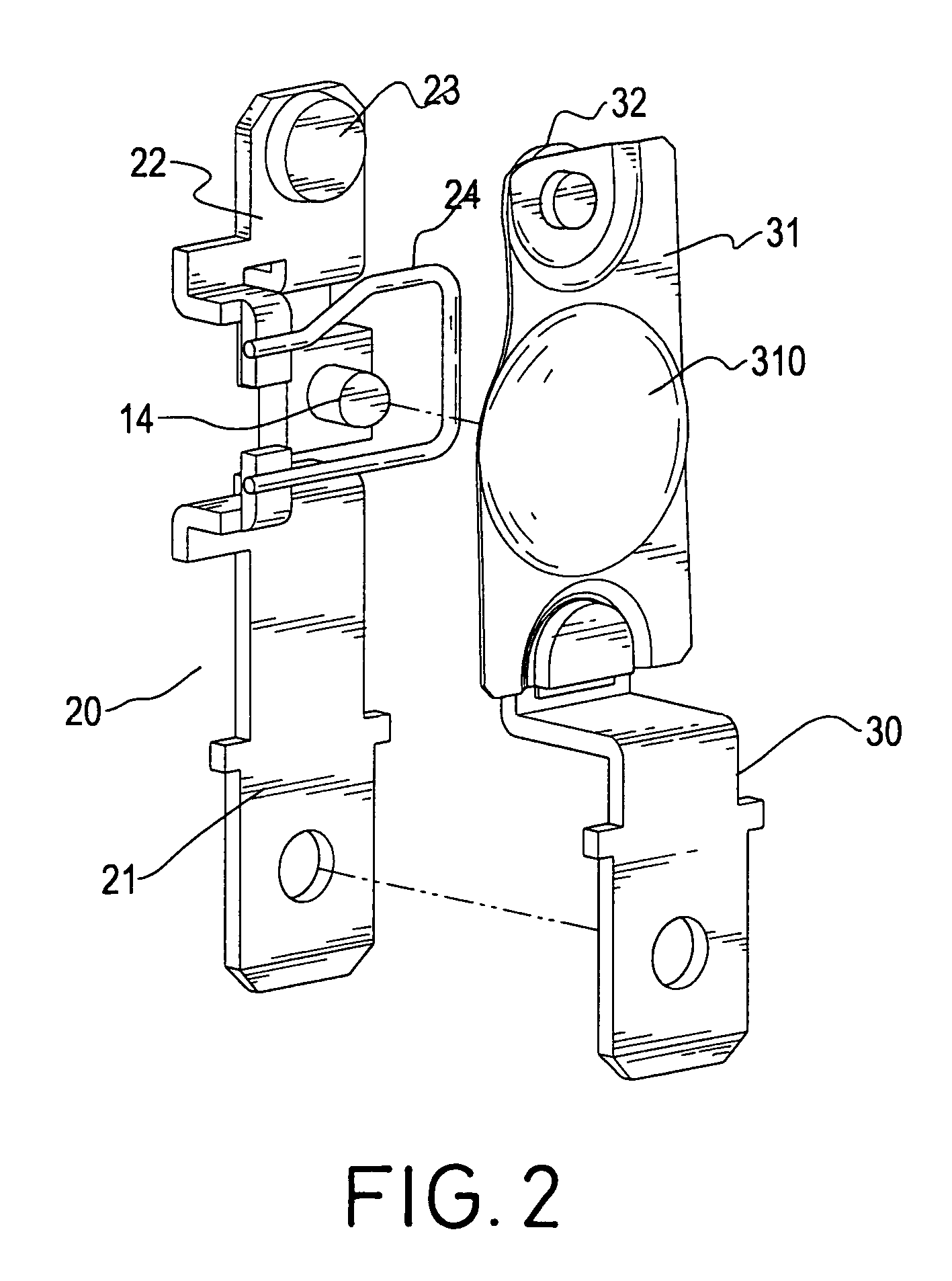
[0020]The primary leg (20) is securely attached to an inner side of the housing (10) and divided into a first portion (21) partially extending out of the housing (10) and a second portion (22) received in the housing (10). The second portion (22) is provided with a first contact (23) formed on a distal end of the second portion (22). A conductor (24) is provided to be sandwiched between the first portion (2...


PUM


Abstract

An overload protection switch has a conductor interconnecting the first primary leg and a second primary leg so that when current passes through the switch, the current not only raises the temperature of the bi-metal plate, but also raises the temperature of the conductor to enhance the deformation of the bi-metal plate such that the electrical appliance connected to the switch and having an ampere tolerance lower than that of the bi-metal plate is protected.

Description

BACKGROUND OF THE INVENTION[0001]1. Field of the Invention[0002]The present invention relates to a switch, and more particularly to an overload protection switch in which a conductor is provided to connect the first primary leg to the second primary leg so that not only will the current passing along the primary leg cause temperature rise in the bi-metal plate, but also the heat generated in the conductor will cause the temperature of the bi-metal plate to rise so that overload to the switch is avoided.[0003]2. Description of Related Art[0004]Overload protection devices provided for safety when using electrical appliances are commonly used in our daily lives. FIGS. 5 and 6 show a conventional overload protection switch. The switch has a hollow housing (50) and a button (60).[0005]The button (60) has two bosses (600) respectively formed on two opposite sides of the button (60) to correspond to two pivot holes (500) respectively defined in opposite sides of an upper portion of the hou...

Claims


Application Information

Patent Timeline
Patent Type & Authority Patents(United States)
IPC IPC(8): H01H73/26H01H37/52H01H73/30H01H71/16
CPCH01H73/26H01H71/164
Inventor HUANG, ALBERT
Owner HUANG ALBERT
Why Eureka
Try Eureka