Method for determining energy efficiency of an energy system in a hybrid vehicle

a technology of energy system and hybrid vehicle, which is applied in the direction of process and machine control, battery/fuel cell control arrangement, instruments, etc., can solve the problems of only being able to test and verify the system, unable or impossible to manufacture an electrical component within a specified tolerance, and only being able to fully assembled

Inactive Publication Date: 2016-02-11
VOLVO LASTVAGNAR AB
View PDF5 Cites 6 Cited by
  • Summary
  • Abstract
  • Description
  • Claims
  • Application Information

AI Technical Summary

Benefits of technology

[0019]By determining a measure, such as a ratio or difference, representative of a relation between the electrical brake energy and the mechanical brake energy of a first and a second vehicle retardation, a measure of the actual efficiency of the energy system can be obtained. It is of advantage if the time period between the retardations is relatively long, such that a measurable difference can be detected. The time period between the first and the second retardation is preferably several months or more. The measured retardation values are preferably stored in a memory.
[0020]It is a

Problems solved by technology

Such a system can only be tested and verified when completely assembled.
Some system can only be tested and verified when mounted on the vehicle, since they require input from other systems.
It is e.g. fairly easy and cost-effective to manufacture valves within tight tolerances, but more difficult or impossible to manufacture an electrical component within a specified tolerance, especially batteries.
This is a costly and time-consuming operation.
Further, this grouping may only be valid when the component is new, since different components may age differently.
Some components are known to degrade with age.
For some components, e.g. lamps, it is more or less impossible to predict the degradat

Method used


Image

  • Method for determining energy efficiency of an energy system in a hybrid vehicle
  • Method for determining energy efficiency of an energy system in a hybrid vehicle
  • Method for determining energy efficiency of an energy system in a hybrid vehicle

Examples


Embodiment Construction

[0025]The embodiments of the invention with further developments described in the following are to be regarded only as examples and are in no way to limit the scope of the protection provided by the patent claims.

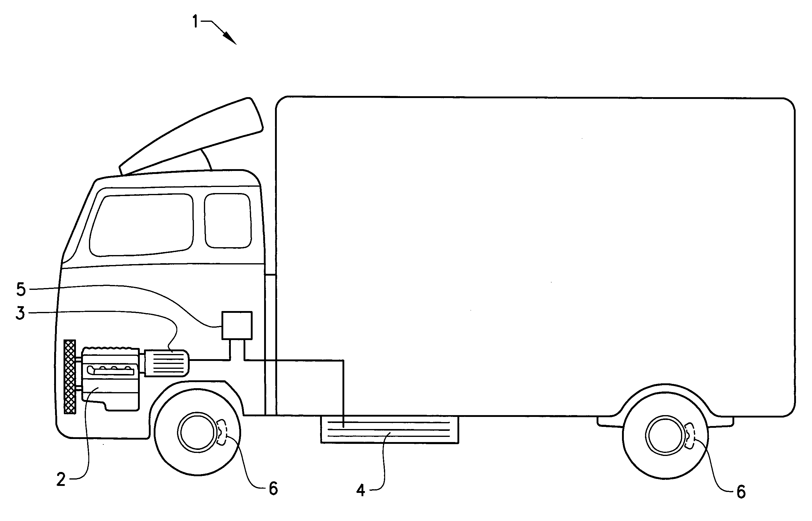
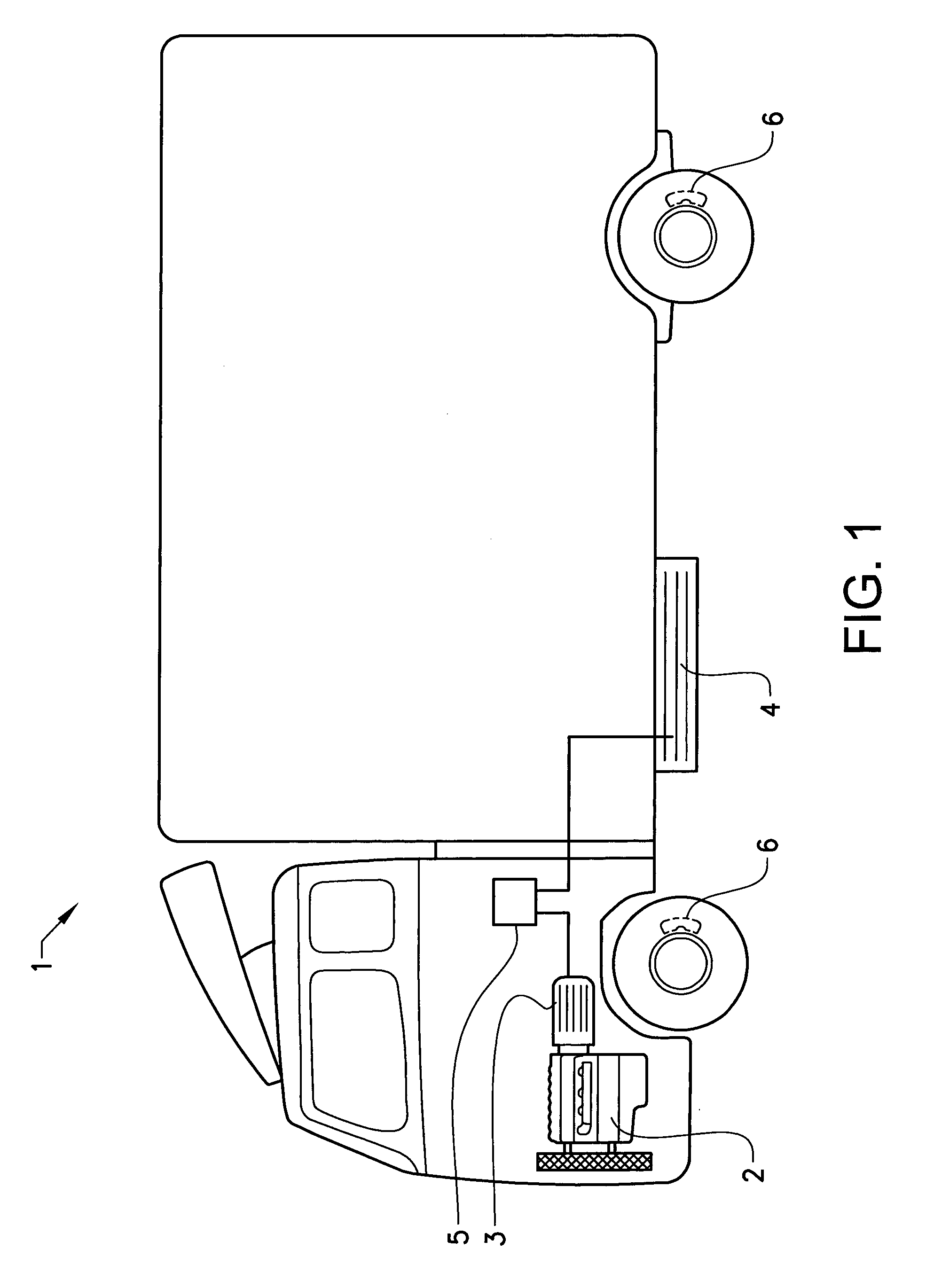
[0026]FIG. 1 shows a schematic hybrid vehicle 1, here shown as a delivery truck. The hybrid vehicle may be a regular hybrid vehicle or a plug-in hybrid vehicle. Other types of heavy hybrid vehicles such as buses., refuse vehicles, wheel loaders etc. can also be used with the inventive method. The hybrid vehicle is provided with a combustion engine 2, normally a diesel engine but other types of fuels, such as liquefied natural gas or compressed natural gas, can of coarse also be used. The hybrid vehicle is also provided with an electric machine 3 connected to the engine. The electric machine is preferably positioned close to the engine but can also be placed apart from the engine, e.g. at the drive axle of the vehicle. The vehicle is provided with service brakes 6 on all whe...


PUM


Abstract

A method for determining the efficiency of an electric energy system of a hybrid vehicle includes determining a measure representative of a relation between the electrical, brake energy and the mechanical brake energy, by determining a requested brake energy for a first vehicle retardation, and by determining an actual electrical brake energy and the actual mechanical brake energy during the vehicle retardation, determining a new measure representative of a relation between the electrical brake energy and the mechanical brake energy at a subsequent second similar vehicle retardation, comparing the determined measures representative of a relation between the electrical brake energy and the mechanical brake energy of the first and second vehicle retardations, where the actual efficiency of the energy system is obtained from the change in the measure representative of a relation between the electrical brake energy and the mechanical brake energy of the first and second vehicle retardations.

Description

BACKGROUND AND SUMMARY[0001]The present invention relates to a method for determining the energy efficiency of the energy system in a hybrid vehicle.[0002]Vehicles and vehicle components are tested during manufacture of the vehicle. Most components can be tested and verified at the sub-supplier when the component is manufactured. However, many components are comprised in a system in which several different components make up the system. Such a system can only be tested and verified when completely assembled. Some system can only be tested and verified when mounted on the vehicle, since they require input from other systems.[0003]Some components and systems have greater deviations than other. It is e.g. fairly easy and cost-effective to manufacture valves within tight tolerances, but more difficult or impossible to manufacture an electrical component within a specified tolerance, especially batteries. The only way to arrive at a required tolerance may then be to manufacture several c...

Claims


Application Information

Patent Timeline
IPC IPC(8): B60W40/12B60L3/12B60L7/10B60L11/18B60L50/16B60W20/00
CPCB60W40/12B60L7/10Y10S903/947B60L3/12B60W20/00B60L11/1851B60L7/12B60L7/26B60L15/2009B60L2200/36B60L2240/12B60L2240/421B60L2240/423B60L2240/441B60L2240/443B60L2240/545B60L2240/547B60L2240/549B60W30/18127B60W2050/0075B60W2510/248B60Y2300/89B60L50/16B60L50/66B60L58/12B60L58/16B60L58/10B60W2556/10Y02T10/64Y02T10/70Y02T10/7072Y02T10/72
Inventor STORM, JONASKJELLBERG, JORGEN
Owner VOLVO LASTVAGNAR AB
Why Eureka
Try Eureka