Sheath Heater

a technology of sheath heater and heat sink, which is applied in the direction of heating element shapes, lighting and heating apparatus, combustion process, etc., can solve the problems of high cost of heat pressing method, high cost, and inability to meet the needs of small-scale production,

Inactive Publication Date: 2003-06-12
ROBERT BOSCH GMBH
View PDF0 Cites 3 Cited by
  • Summary
  • Abstract
  • Description
  • Claims
  • Application Information

AI Technical Summary

Problems solved by technology

However, sheathed-type glow plugs having this type of design can only be manufactured using expensive heat pressing methods.
Sheath heaters of this type that are known from the related art have the disadvantage that they have a hot zone that must be created in an extremely finely fashion by forming a pointed tip or otherwise reducing the cross-section in the area of the tip of the sheath heater, in order to be able to be heated rapidly to a high temperature.
However, filigree tips of sheath heaters, that are therefore only capable of standing up to small stresses, are extremely sensitive and can be easily damaged, especially during handling, installation in the engine, etc.
Furthermore, areas of sheath heaters that are reduced in their cross-section in this manner also have an insufficient thermal mass, so that it is impossible to achieve satisfactory temperature stability, and therefore in response to a sudden cooling in the environment, such as during a cold start of the engine, the danger of blowing out the sheathed-type glow plug is very great.

Method used


Image

  • Sheath Heater
  • Sheath Heater
  • Sheath Heater

Examples


Embodiment Construction

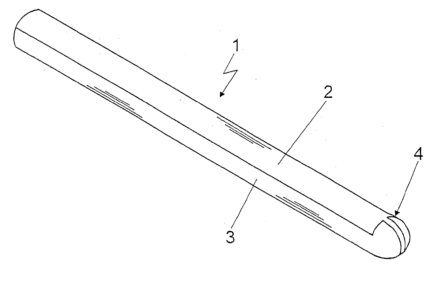
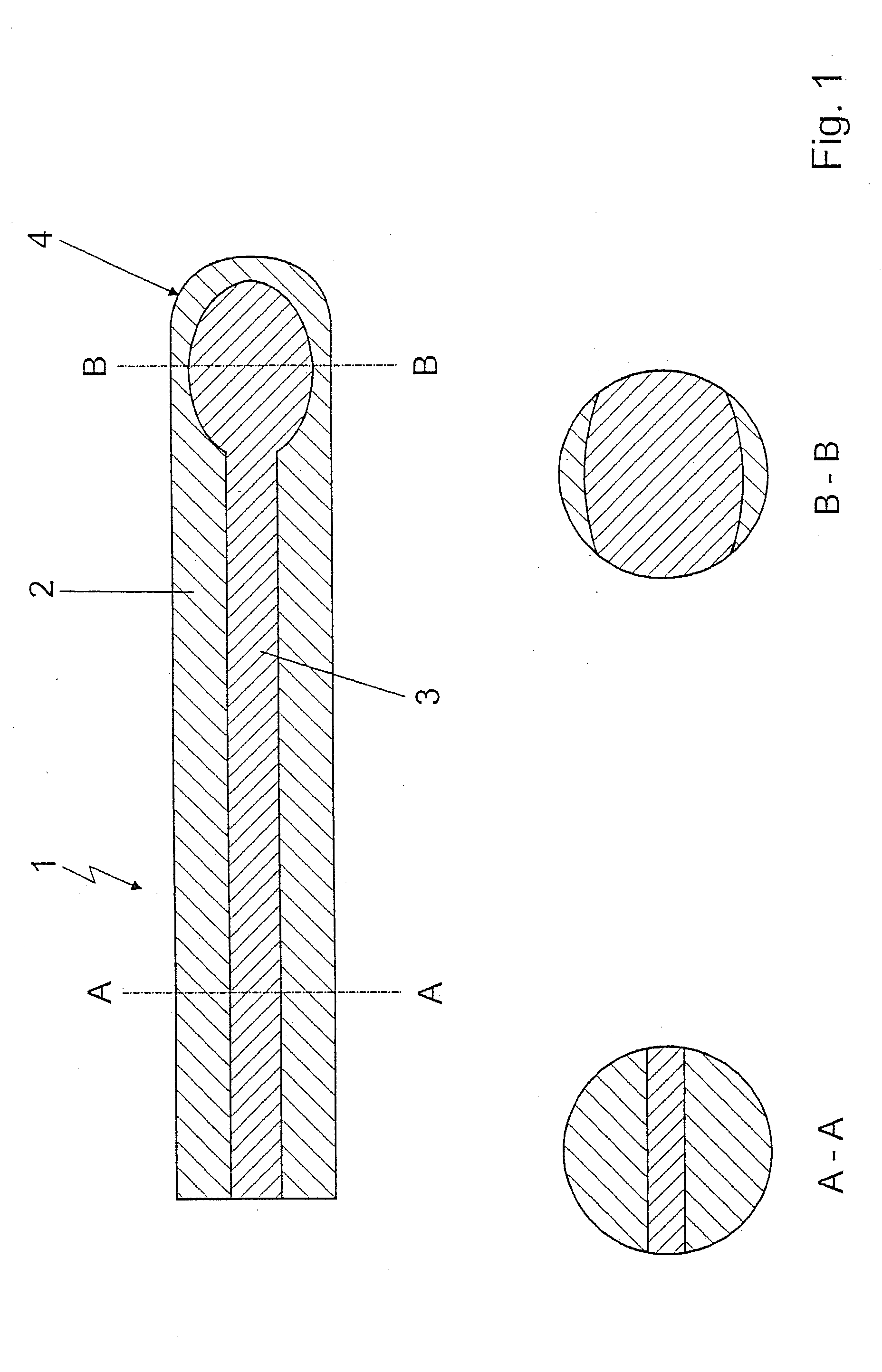
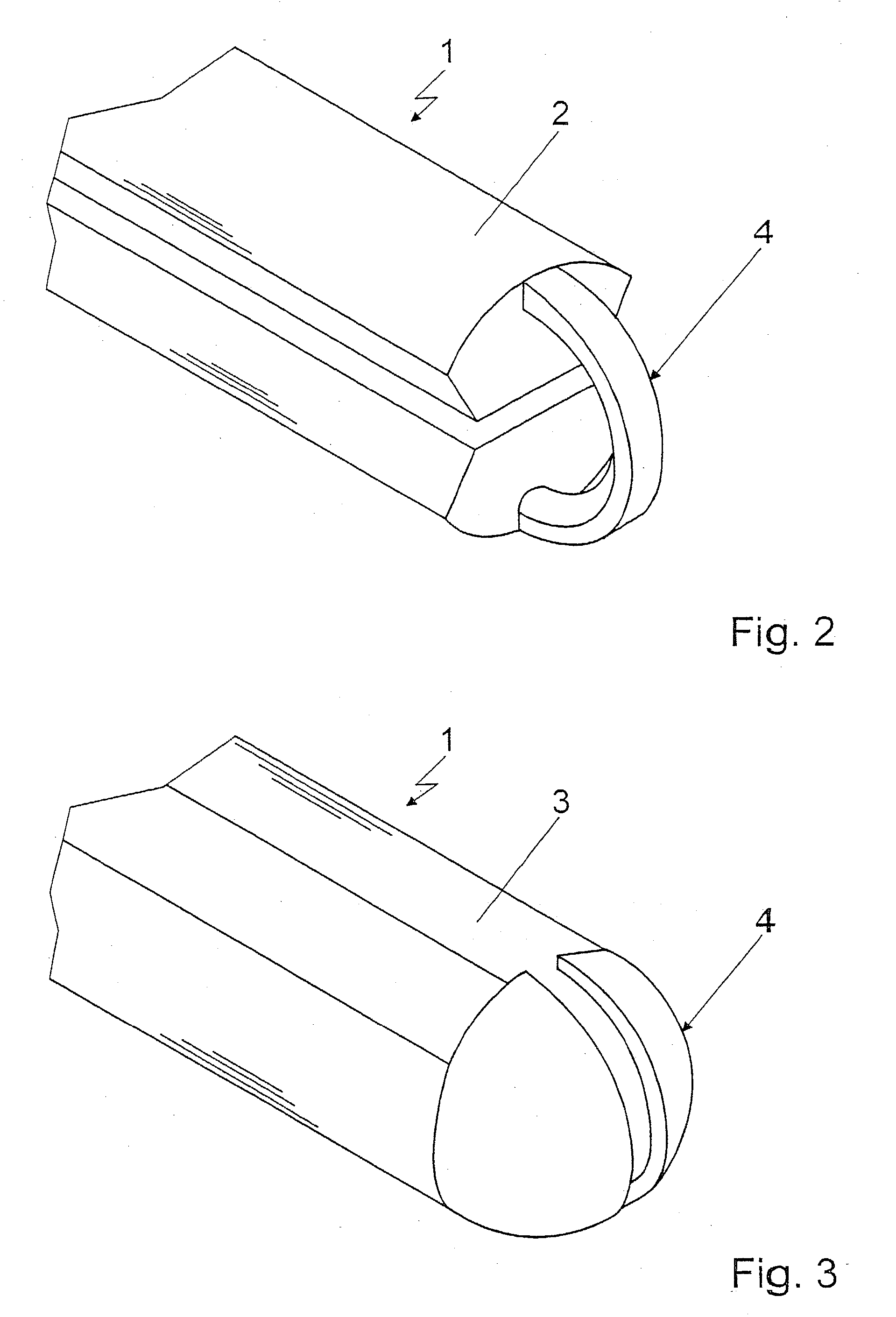
[0028] In FIG. 1, a sheath heater 1 is depicted in a longitudinal cutaway view, a conductive layer 2 being essentially external and an insulation layer 3 being essentially internal, insulation layer 3 being surrounded by conductive layer 2 in a sandwich-like manner. Both layers 2, 3 constitute a ceramic composite structure.

[0029] This sheath heater 1, as can be seen in FIG. 1, has a uniform overall cross-section over its entire length, insulation layer 3 in the area of a tip 4 of sheath heater 1 undergoing a cross-sectional expansion, whereas the portion of external conductive layer 2 is correspondingly reduced in comparison to the overall cross-section.

[0030] As can be seen, in particular, from the appropriate cross-sections along the lines A-A and B-B in FIG. 1, the sheath heater according to the preferred embodiment is configured in a symmetrical fashion. Symmetrical, in this context, can denote a symmetry about an axis of symmetry lying in the cross-sectional plane, or a symmetr...


PUM


Abstract

A sheath heater in a sheathed-type glow plug for diesel engines is described, having at least one generally internal insulation layer and at least one generally external conductive layer, both layers making up a ceramic composite structure. The sheath heater has a generally uniform overall cross-section, generally over its entire length, and, in the area of a tip of the sheath heater, the proportion of the insulation layer in the overall cross-section increases, whereas the proportion of the conductive layer in the overall cross-section decreases.

Description

BACKGROUND INFORMATION[0001] The present invention relates to a sheath heater, especially for use in a sheath-type glow plug for diesel engines, in accordance with the type defined in greater detail in the preamble of Patent claim 1.[0002] The technology of modern diesel engines places great demands on sheathed-type glow plugs, especially with regard to size, sturdiness, rapidity of heating-up, and resistance to high temperatures. It is usually desirable that, at a heater output of roughly 70 to 100 W, a temperature of 1000.degree. C. and a steady-state temperature of 1200.degree. C. can be achieved within 2 seconds.[0003] From practice, sheathed-type glow plugs are familiar today that have metallic and ceramic heaters. Customary designs of ceramic sheathed-type glow plugs have internal metallic or ceramic heaters, which are sintered into a nonconductive ceramic that is stable at high temperatures. However, sheathed-type glow plugs having this type of design can only be manufactured...

Claims


Application Information

Patent Timeline
Patent Type & Authority Applications(United States)
IPC IPC(8): H05B3/16F23Q7/00H05B3/46
CPCF23Q7/001
Inventor LINDEMANN, GERTAICHELE, WILFRIEDREISSNER, ANDREASLINDNER, FRIEDERICKERAU, CHRISTOFKNOLL, GUENTER
Owner ROBERT BOSCH GMBH
Why Eureka
Try Eureka