Methods and apparatus for network congestion control

a network congestion and control method technology, applied in the field of network congestion control, can solve the problems of blocking over a much wider portion, rough technique, and inability to allow end and buffer-to-buffer flow control mechanisms

Active Publication Date: 2003-06-19
CISCO TECH INC
View PDF33 Cites 119 Cited by
  • Summary
  • Abstract
  • Description
  • Claims
  • Application Information

AI Technical Summary

Problems solved by technology

End-to-end and buffer-to-buffer flow control mechanisms do not allow a first network node to transmit to a second network node until a second network node is ready to receive a frame.
However, end-to-end and buffer-to-buffer flow control mechanisms provide only a very rough technique for controlling congestion, as the mechanism blocks all traffic along a particular link.
Hence, congestion at one link of one network p

Method used


Image

  • Methods and apparatus for network congestion control
  • Methods and apparatus for network congestion control
  • Methods and apparatus for network congestion control

Examples


Embodiment Construction

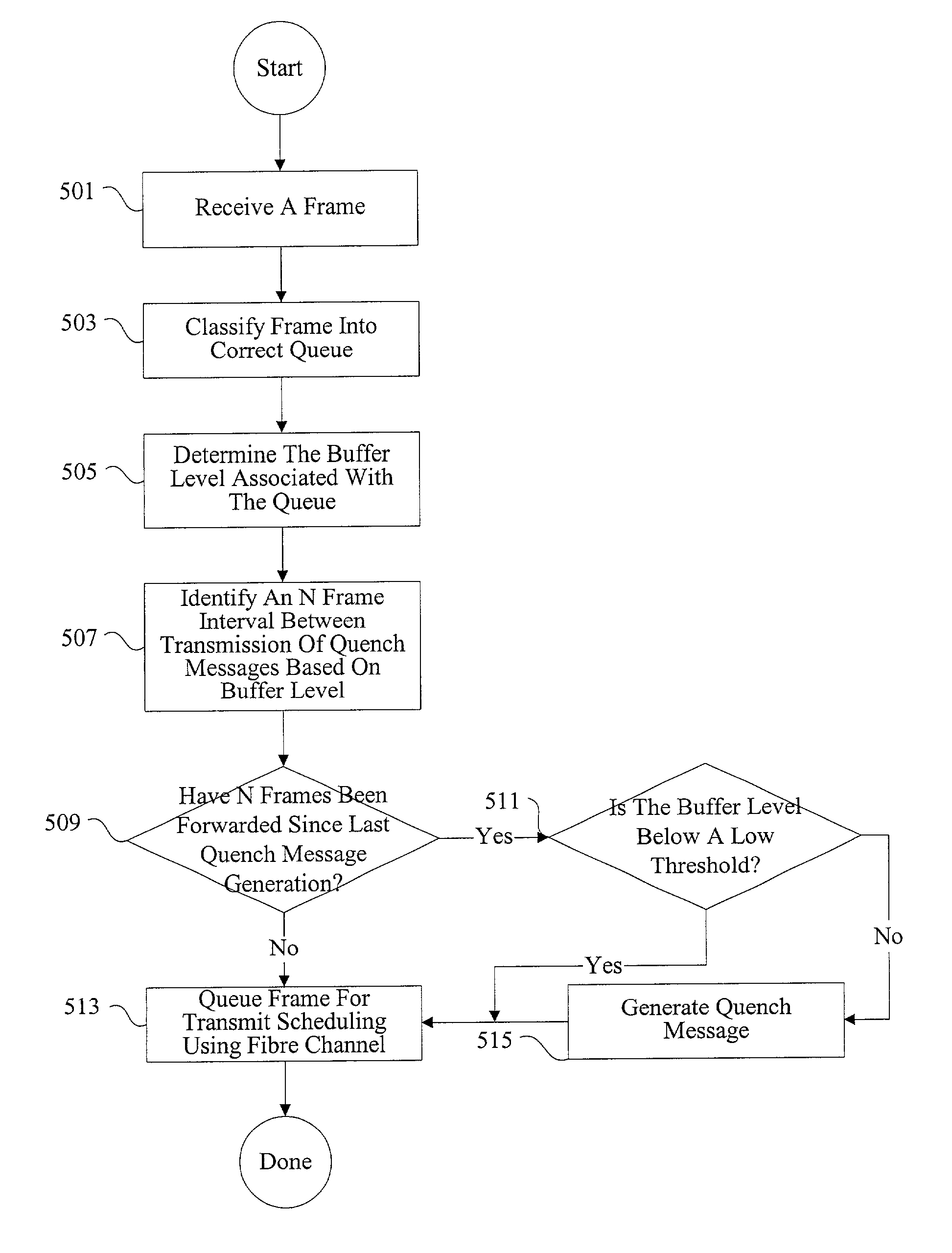
[0029] The present invention relates to controlling congestion in a network. More specifically, the present invention relates to methods and apparatus for transmitting quench messages from a congested network node to other network nodes to control the traffic flow to the congested network node.

[0030] Reference will now be made in detail to some specific embodiments of the invention including the best modes contemplated by the inventors for carrying out the invention. Examples of these specific embodiments are illustrated in the accompanying drawings. While the invention is described in conjunction with these specific embodiments, it will be understood that it is not intended to limit the invention to the described embodiments. On the contrary, it is intended to cover alternatives, modifications, and equivalents as may be included within the spirit and scope of the invention as defined by the appended claims.

[0031] For example, the techniques of the present invention will be describe...


PUM


Abstract

Methods and apparatus are provided for controlling congestion in a network such as a fibre channel network. Techniques are provided for characterizing traffic flow at a congested network node. The congested network node can generate various instructions such as quench messages to control traffic flow towards the congested network node. The quench messages can optionally include information about the characteristics of the congestion. The instructions are distributed to other nodes in the network. The other network nodes can interpret the instructions and control traffic flow towards the congested node.

Description

[0001] 1. Field of the Invention[0002] The present invention relates to network congestion control. More specifically, the present invention relates to methods and apparatus for detecting congestion, generating instructions for alleviating congestion, distributing the instructions, and controlling congestion.[0003] 2. Description of Related Art[0004] Many conventional network protocols use packet dropping to alleviate congestion at a network node. In one example, a network node in an IP based network receives input data from multiple sources at a rate exceeding its output bandwidth. In conventional implementations, selected packets are dropped to allow transmission of remaining packets within the allocated output bandwidth. Packets can be dropped randomly or by using various selection criteria. The dropped packets are ultimately retransmitted under the control of a higher level protocol such as TCP.[0005] In networks such as fibre channel networks, packet dropping is generally not a...

Claims


Application Information

Patent Timeline
IPC IPC(8): G06F15/16H04L47/30
CPCH04L47/12H04L47/17Y02B60/31H04L47/266H04L47/30H04L47/263Y02D30/50H04L47/38
Inventor COMETTO, MAURILIOMORANDIN, GUGLIELMO M.KLOTH, RAYMOND J.HOFFMAN, ROBERT L.
Owner CISCO TECH INC
Why Eureka
Try Eureka