Optical head device and objective lens

Inactive Publication Date: 2003-07-03
DIMENSIONAL DYNAMICS LLC +1
View PDF2 Cites 4 Cited by
  • Summary
  • Abstract
  • Description
  • Claims
  • Application Information

AI Technical Summary

Benefits of technology

[0015] Also, the refractive grating may be designed to be optimum for refracting the second laser beam toward a beam spot forming position. Accordingly, the diffraction grating can be readily designed.
[0016] In addition, due to the fact that predetermined portions of the first and second laser beams that are important to form beam spots are passed through the objective lens without being diffracted, the use efficiency of the laser beams can be improved.
[0017] A second diffraction grating that diffracts the first laser beam so as not to converge on the beam spot forming position may be formed over the entire area of the outer circumferential refracting surface region. By so doing, unnecessary beam components on the outer circumferential portions of the first laser beam can be eliminated without using an aperture stop.

Problems solved by technology

However, since the objective lens described above is designed on the premise that a laser beam with a single wavelength is converged at two different focal points, this objective lens is not suitable for a two-wavelength light source type optical head device that uses laser beams with different wavelengths, such as an optical head device equipped with a light source for a laser beam with a wavelength of 780 nm to be used for reproducing and recording data on a compact disk recordable (CD-R) and a light source for a laser beam with a wavelength of 650 nm to be used for reproducing data on a DVD.
This forces a severe burden on designing the diffractive grating, and invites deterioration of the light utility efficiency.

Method used


Image

  • Optical head device and objective lens
  • Optical head device and objective lens
  • Optical head device and objective lens

Examples


Embodiment Construction

[0048] Examples of optical head devices equipped with objective lenses in accordance with embodiments of the present invention are described below with reference to the accompanying drawings.

[0049] (Overall Composition)

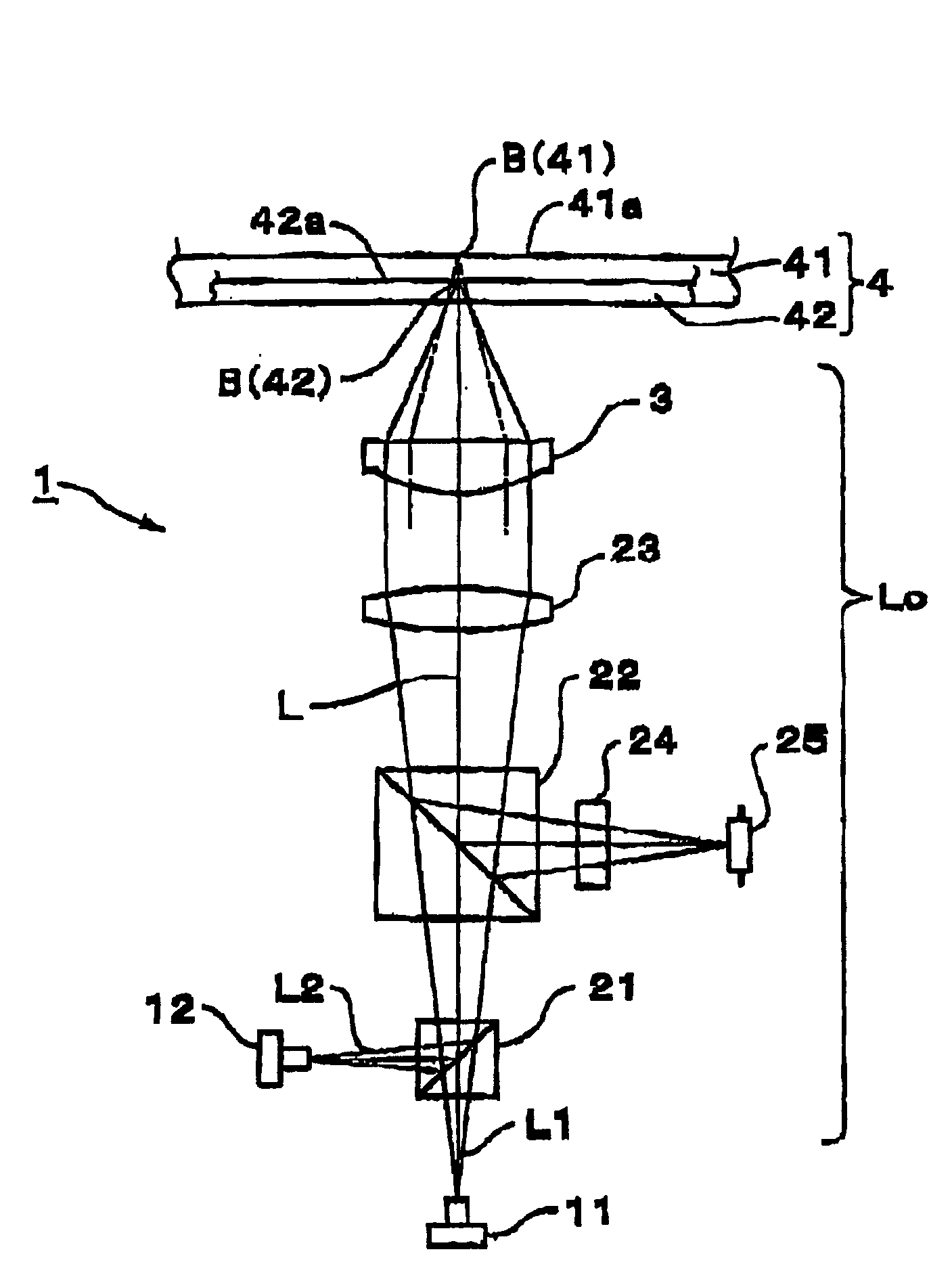
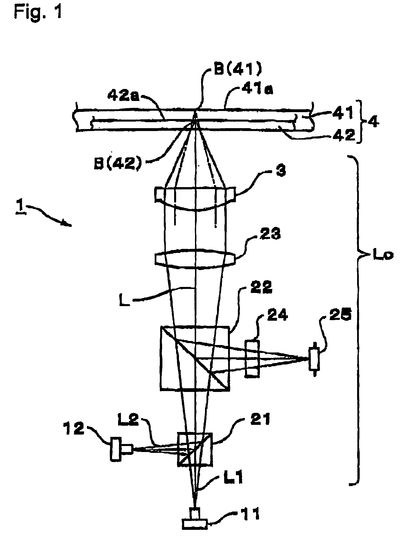
[0050] FIG. 1 schematically shows a structure example of an optical head device 1 illustrated based on its optical system in accordance with the present invention. The optical head device 1 of the present example can reproduce and record information on an optical recording medium 4 in multiple kinds that are different in substrate thickness and recording density, such as a CD, CD-R, DVD or the like. For this reason, the optical head device 1 is equipped with two laser beam sources, i.e., a first laser beam source 11 and a second laser beam source 12. The first laser beam source 11 emits a first laser beam L1 with a central wavelength of 780 nm for reproducing information on a CD-R, for example, and the second laser beam source 12 emits a second laser beam L2 with a wa...


PUM


Abstract

An optical head device that converges first and second laser beams having different wavelengths on recording surfaces of first and second optical recording media through a single light converging optical system including an objective lens for recording or reproducing data on the recording surfaces. A refracting surface of the objective lens is divided into two regions, i.e., a central refracting surface region with an optical axis thereof being as a center and an outer circumferential refracting surface region that surrounds an outer circumference of the central refracting surface region. A diffraction grating is formed generally entirely over the central refracting surface region. When recording or reproducing data on the first optical recording medium using the first laser beam, a beam spot is formed with a diffracted beam obtained by the central refracting surface region. When recording or reproducing data on the second optical recording medium using the second laser beam, a beam spot is formed with a beam portion that passes the outer circumferential refracting surface region and a diffracted beam obtained by the central refracting surface region.

Description

[0001] 1. Field of the Invention[0002] The present invention relates to an optical head device for protecting and recording data on optical recording media such as compact disks (CDs) and digital video disks (DVDs) that have different substrate thickness by using laser beams having different wavelengths. Moreover, the present invention relates to objective lenses that are suitable for such optical head device.[0003] 2. Related Background Art[0004] Optical recording media having transparent substrates for protecting recording surfaces with different thickness and different recording density such as CDs and DVDs are known. For example, each CD is provided with a transparent substrate for protecting its recording surface whose thickness is 1.2 mm, while each DVD is provided with a transparent substrate that is thinner than that of the CD, which is 0.6 mm, and has a higher recording density than that of the CD.[0005] There have been proposed optical head devices that record and reproduc...

Claims


Application Information

Patent Timeline
IPC IPC(8): G11B7/00G11B7/135
CPCG11B7/1353G11B2007/13727G11B2007/0006G11B7/1374
Inventor FUJITA, YUJIHAYASHI, KENICHIMIYASAKA, YOSHIFUSAAZUMA, TAKAHIROOKAMURA, TETSURO
Owner DIMENSIONAL DYNAMICS LLC
Why Eureka
Try Eureka