Multiple port fluid control valves

a fluid control valve and multi-port technology, applied in the direction of process and machine control, mechanical equipment, instruments, etc., can solve the problems of damage or malfunction of the transducer, a considerable degree of training to learn how to properly operate one of the prior art manifolds, and high manufacturing costs

a fluid control valve and multi-port technology, applied in the direction of process and machine control, mechanical equipment, instruments, etc., can solve the problems of damage or malfunction of the transducer, a considerable degree of training to learn how to properly operate one of the prior art manifolds, and high manufacturing costs

US20030125673A1Inactive Publication Date: 2003-07-03MEDLINE INDUSTRIES

Image

  • Multiple port fluid control valves
  • Multiple port fluid control valves
  • Multiple port fluid control valves

Examples


Embodiment Construction

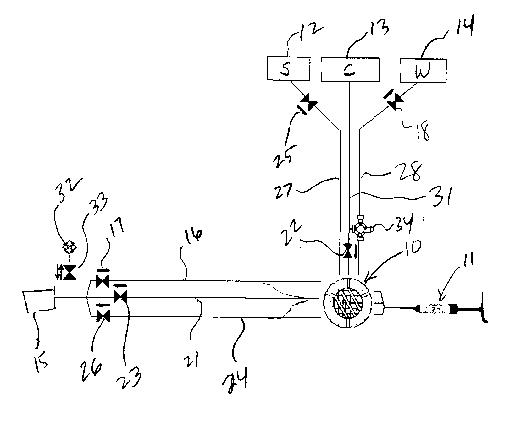
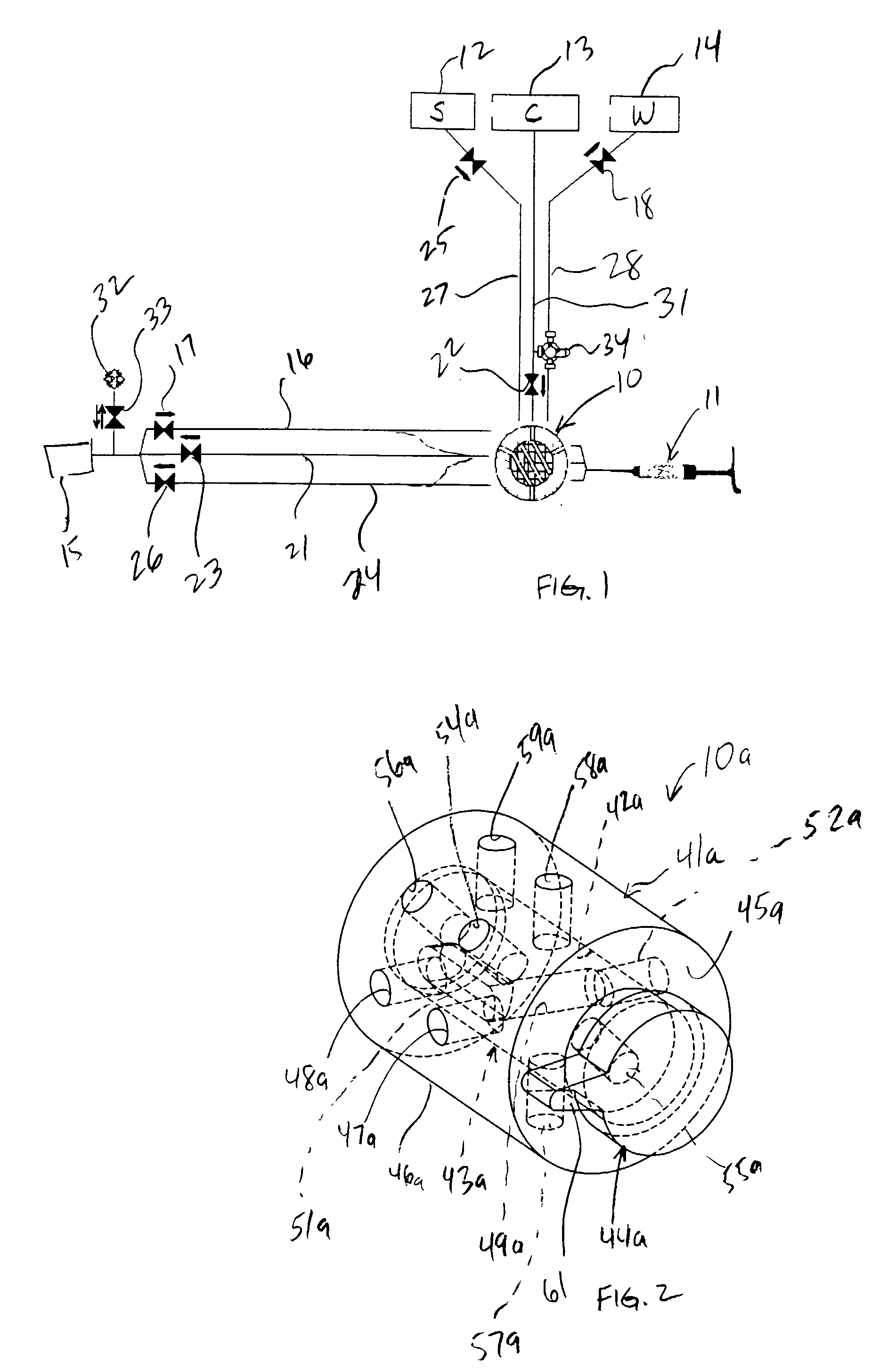
[0062] FIG. 1 illustrates a fluid control valve 10 as coupled to injector 11, a saline supply 12, a contrast supply 13, and a waste dump or reservoir 14. The control valve 10 is also coupled to a catheter, shown schematically at 15. In the embodiment illustrated in FIG. 1, three lines couple the control valve 10 to the catheter 15. A waste line 16 equipped with a one-way valve 17 communicates waste fluid from the catheter 15 through the valve 10, through the one-way valve 18 to the waste reservoir 14. The operation of the valve 10, and numerous refinements thereof, will be explained below. The contrast line 21 communicates fluid drawn from the contrast reservoir 13 through the one-way check valve 22, through the valve 10, and through the one-way check valve 23 to the catheter 15. Finally, the saline line 24 communicates saline drawn from the saline reservoir 12 through the one-way check valve 25, to the valve 10, through the one-way check valve 26 to the catheter 15.

[0063] The one-w...


PUM


Abstract

A fluid control valve is disclosed which, with a single valve, can manipulate flow between a saline supply, a contrast supply, a waste dump and a catheter. The control valve includes three primary positions including a contrast position where the valve provides communication between an injector and a contrast supply while isolating the saline supply and catheter. The valve also can be moved to a saline / waste position where the valve provides communication between the injector and the saline supply and / or the waste dump while isolating the contrast supply and catheter. The valve also can be moved to an injection position where the valve provides communication between the injector and the catheter. A single valve provides all three functions. The valve also may provide communication between a pressure transducer and catheter during the saline loading, waste dumping and contrast loading functions. The valve also provides protection or isolation of the pressure transducer during injection procedures.

Description

[0001] This application claims the benefit under 35 U.S.C. .sctn.119(e) of U.S. provisional patent application serial No. 60 / 326,941 filed Oct. 4, 2001, the disclosure of which is incorporated herein by reference.[0002] A fluid control valve is disclosed. More specifically, a fluid control valve that selectively controls a flow of fluid between multiple input and output ports and that selectively provides communication between a pressure transducer port and an output port and that selectively isolates the pressure transducer port is disclosed. The disclosed fluid control valve is used to control various fluids injected during intravascular medical procedures. More specifically, the disclosed fluid control valve facilitates the control and injection of contrast and saline solutions during an intravascular procedure. Background of the Related Art Various medical procedures involve the introduction of fluids into the body of a patient using a catheter. When a series of different fluids...

Claims


Application Information

Patent Timeline
03 Jul 2003
Publication
US20030125673A1
IPC
A61M39/00; A61M5/168; A61M39/22; F16K11/085
CPC
A61M5/16827; F16K11/0856; A61M39/223
Inventors
HOUDE, ERIC; VAN DIVER, MARK