Manifold for a horn loudspeaker and method

a manifold and horn technology, applied in the field of manifolds for horn loudspeakers, can solve the problems of increasing the distortion of the sound pressure wave as it passes through the waveguide, and achieve the effect of reducing the distortion

Inactive Publication Date: 2003-07-17
MEYER SOUND LABORATORIES
View PDF0 Cites 39 Cited by
  • Summary
  • Abstract
  • Description
  • Claims
  • Application Information

AI Technical Summary

Benefits of technology

[0008] For a horn whose elongated throat opening is oriented vertically, the manifold provides a vertical line array of output ports to simulate a vertical column of individual acoustic power sources in the throat of the horn. These individual acoustic power sources interact in accordance with well-known line array theory to control vertical dispersion from the line array. Thus, the vertical dispersion characteristics of the horn connected to the manifold are mainly governed by the line array characteristics of the horn's elongated throat opening instead of by the design characteristics of the horn itself. The horn provides an additional element of directional control, and acts to block any side lobes that may be generated at the horn's throat end by physical separation of the output ports of the driver manifolds.
[0010] In still a further aspect of the invention, each of the manifold waveguides increases in cross-sectional area from the input port of the manifold to the output port of each waveguide. Such expansion acts to further reduce the distortion effects the waveguide has on the acoustic sound waves as they pass through the manifold.

Problems solved by technology

Manifolds substantially exceeding 3 inches in length would produce relatively long acoustical path lengths between the input port and aligned output ports of the manifold at high frequencies, resulting in increased distortion in the sound pressure wave as it passes through the waveguides.

Method used


Image

  • Manifold for a horn loudspeaker and method
  • Manifold for a horn loudspeaker and method
  • Manifold for a horn loudspeaker and method

Examples


Embodiment Construction

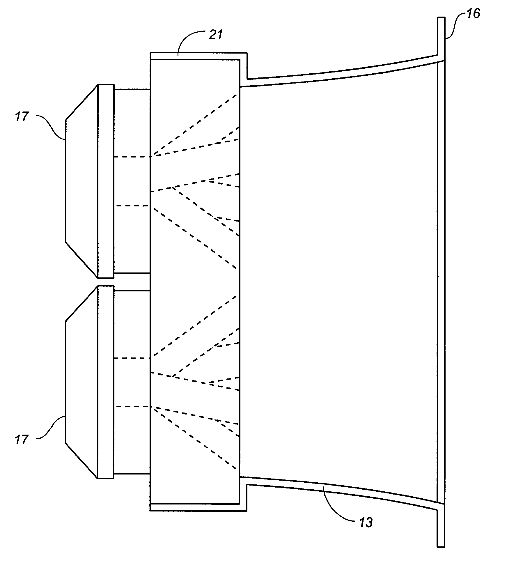
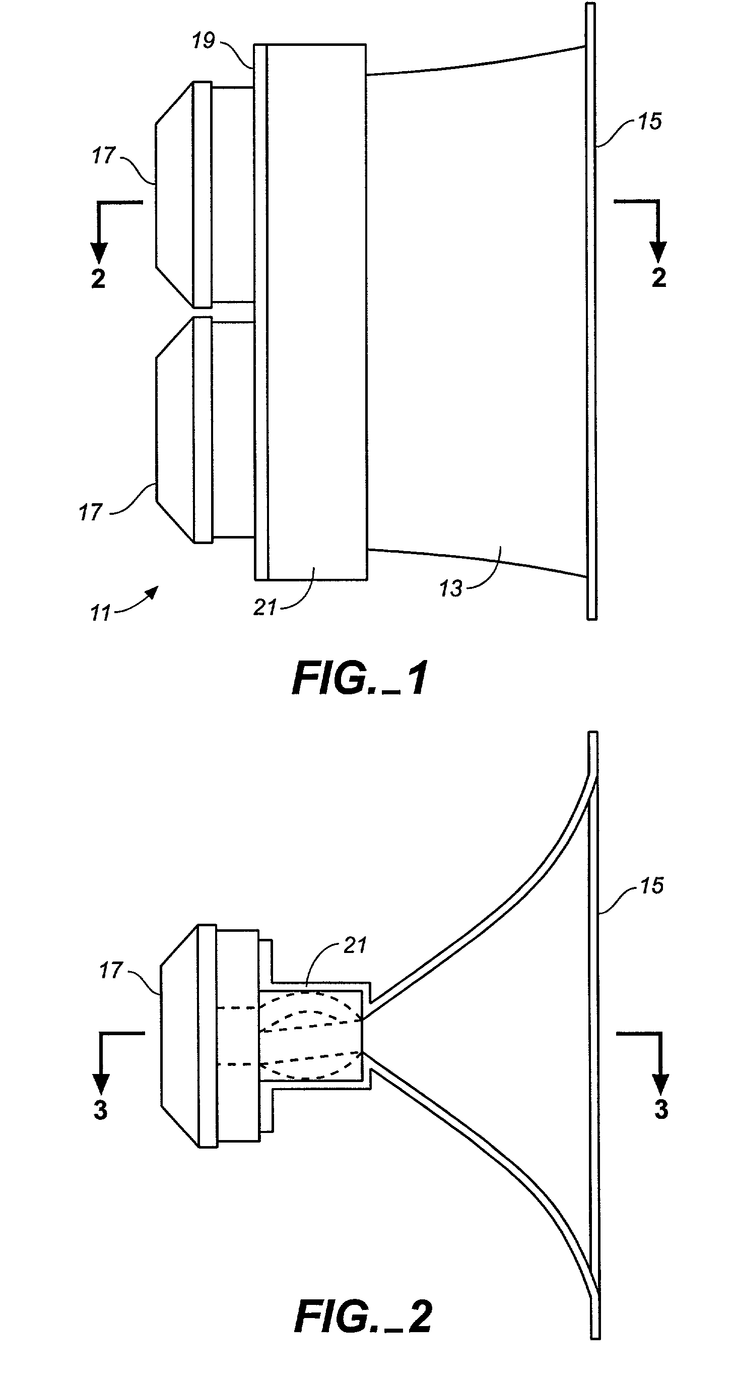
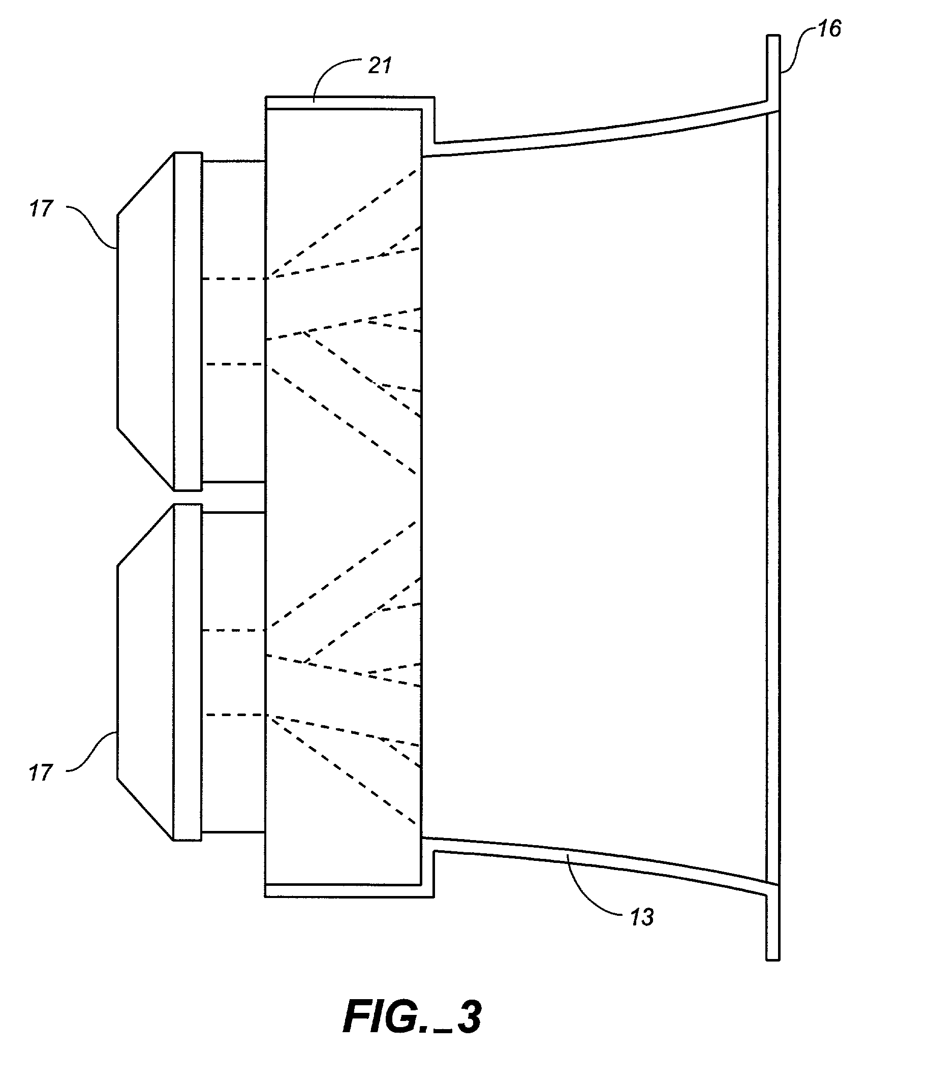
[0043] Referring to FIGS. 1-3 of the drawings, a horn loudspeaker system 11 includes a horn 13 having mouth end 15 and two closely spaced compression drivers 17 mounted to the horn's back end 19. The back end of the horn has an enlarged manifold mounting chamber 21 for holding the driver manifold hereinafter described. The placement of the driver manifold in mounting cavity 21 is illustrated in FIGS. 2 and 3, where a manifold is indicated by a phantom line representation of the acoustic power waveguides of a two driver manifold as hereinafter described.

[0044] The design of the horn of the horn loudspeaker system shown in FIGS. 1-3 is further illustrated in FIGS. 4-5. Referring to these figures, it can be seen that the horn's substantially square mouth 15 has a perimeter mounting flange 16 for mounting the horn to a speaker cabinet. As best shown in FIG. 5, flared vertical sidewalls 25 extend inwardly to form an elongated throat opening 27 which extends between slightly flared top an...


PUM


Abstract

A manifold for a horn loudspeaker has an input end having at least one input port for receiving acoustic power from at least one acoustic driver, and an output end for delivering acoustic power to the throat end of the horn. The output end of the manifold has at least two and suitably multiple output ports. An acoustic power waveguide is provided for each output port and connects each of the output ports to the input port of the manifold. Acoustic power received by the input port is divided between the acoustic waveguides such that it is delivered to the aligned output ports to simulate a line array of acoustic power sources.

Description

CROSS-REFERENCE TO RELATED APPLICATIONS[0001] Applicants claim the benefit of provisional application No. 261,113, filed Jan. 11, 2001BACKGROUND OF THE INVENTION[0002] The present invention generally relates to horn loudspeaker systems and more particularly to manifolds for coupling one or more acoustic drivers to a loudspeaker horn. The invention still further relates to improvements in the horn and horn manifold of a horn loudspeaker system which improve the directional characteristics of the loudspeaker without introducing significant distortion. The invention is particularly useful in arraying horn loudspeaker systems to achieve desired coverage while avoiding undesirable interactions between the horns.[0003] To optimize a horn speaker system array, it is often desirable to control the dispersion characteristics of the horn such that the dispersion is narrow in the direction of the array and wide in the direction perpendicular to the array. Thus, in the case of a vertical stack ...

Claims


Application Information

Patent Timeline
Patent Type & Authority Applications(United States)
IPC IPC(8): G10K11/02G10K11/22G10K11/28H04R1/28H04R1/30H04R1/34
CPCG10K11/025G10K11/22H04R1/345H04R1/30G10K11/28
Inventor MEYER, JOHN D.MEYER, PERRINHERR, RICHARD D.
Owner MEYER SOUND LABORATORIES
Why Eureka
Try Eureka