Closed-Loop Control of Rotary Steerable Blades

a technology of rotary steerable blades and closed loops, which is applied in the direction of surveying, drilling machines and methods, and well accessories, etc., can solve the problems of excessive drag, inability to control the total force exerted against the borehole, and difficulty in obtaining consistent and predictable borehole curvature, etc., to prevent excessive borehole friction, reduce housing roll, and promote accurate borehole caliper measurements

Inactive Publication Date: 2009-07-02
SCHLUMBERGER TECH CORP
View PDF42 Cites 36 Cited by
  • Summary
  • Abstract
  • Description
  • Claims
  • Application Information

AI Technical Summary

Benefits of technology

[0007]The present invention addresses the need for improved drilling methods for use in rotary steerable deployments. Aspects of this invention include a steering tool having a controller configured to provide closed-loop control of blade pressure and position. In one exemplary embodiment, the controller is configured to execute a directional control methodology in which the drilling direction is controlled via control of the blade positions....

Problems solved by technology

Therefore, obtaining a consistent and predictable borehole curvature can be difficult.
Moreover the total force exerted against the borehole is typical...

Method used


Image

  • Closed-Loop Control of Rotary Steerable Blades
  • Closed-Loop Control of Rotary Steerable Blades
  • Closed-Loop Control of Rotary Steerable Blades

Examples


embodiment 300

[0039]With reference now to FIG. 4, one exemplary directional drilling method embodiment 300 in accordance with the present invention is depicted in flowchart form. At 302 a downhole tool (such as tool 100) is deployed in a subterranean borehole and drilling commences (e.g., via rotating the drill string). At 304, each of the blades is independently extended (or retracted) to a corresponding predetermined radial position (e.g., calculated based on predetermined target tool face and offset values and a measured borehole caliper). At least one blade, and preferably each of the blades, is further locked at its corresponding radial position, e.g., via closing corresponding valves 254 and 256. At 306 the hydraulic pressure is measured in each of the locked blades, e.g., using corresponding pressure sensors 272. At 308, each of the blade pressures measured in 306 is compared with a predetermined target pressure range. The predetermined target pressure range includes both an upper pressure...

embodiment 400

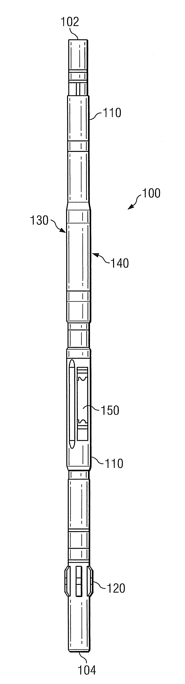
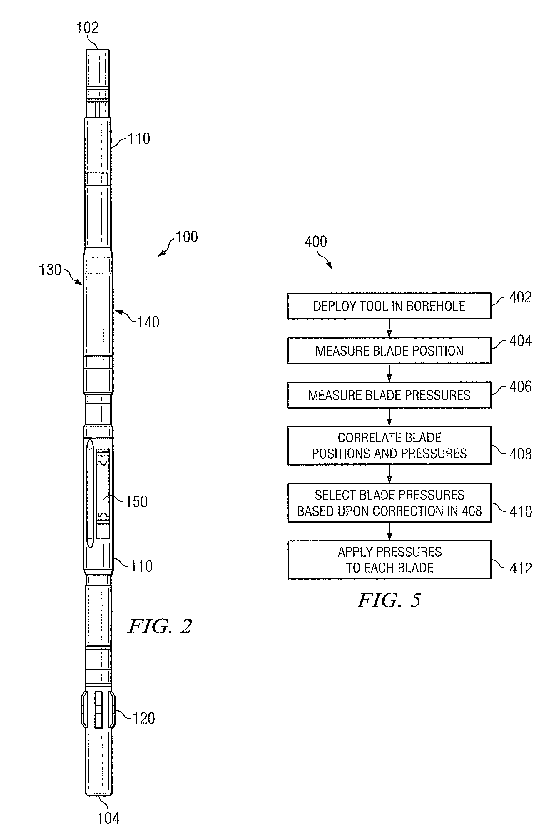
[0057]With reference now to FIG. 5, another exemplary directional drilling method embodiment 400 in accordance with the present invention is depicted in flowchart form. Method 400 is intended to overcome the above described failure of a blade sensor and therefore may potentially (and advantageously) save considerable rig time in the event of such failures. Method 400 is similar to method 300 (depicted in FIG. 4) in that it includes deploying the steering tool in the borehole at 402. The radial position of each of the blades is measured in 404 (e.g., using position sensors 274) and the corresponding pressure in each of the blades is measured in 406 (e.g., using pressure sensors 272). At 408, the blade positions and the measured pressures are then correlated. Such position and pressure measurement and their correlation continues during drilling. For example, the controller may generate a lookup table that includes measured blade pressures as a function of predetermined or measured bla...

embodiment 500

[0060]With reference now to FIG. 6, another exemplary directional drilling method embodiment 500 in accordance with the present invention is depicted in flowchart form. Method 500 depicts one exemplary embodiment by which the blade pressures may be controlled in block 412 of method 400. Predetermined blade pressures are applied at 502. The blade pressures are then measured at 504. If the measured blade pressure is greater than an upper threshold at 506 (e.g., 10 psi above the predetermined pressure), then valve 256 is opened at 508 so as to decrease the pressure in the blade. Valve 256 may then be closed when the pressure drops below the predetermined value. If the measured blade pressure is less than a lower threshold at 510 (e.g., 10 psi below the predetermined pressure), then valve 254 is opened at 512 so as to increase the pressure in the blade. Valve 254 may then be closed when the pressure rises above the predetermined value.

[0061]In certain embodiments it may be advantageous ...


PUM


Abstract

A steering tool has a controller configured to provide closed-loop control of blade pressure and position. In one embodiment, the controller is configured to execute a directional control methodology in which the drilling direction is controlled via control of the blade position. The pressure in each blade is further controlled within a predetermined range of pressures. This embodiment tends to prevent excessive borehole friction while at the same time reducing undesirable rotation of the blade housing. In another embodiment, the controller is configured to correlate blade pressure measurements and blade position measurements during drilling. The correlation is utilized as part of a secondary directional control scheme in the event of a downhole failure of a blade position and/or pressure sensor. This embodiment tends to provide a stable and reliable backup directional control mechanism in the event a sensor failure and therefore may save considerable rig time.

Description

RELATED APPLICATIONS[0001]This application is a continuation-in-part of co-pending, commonly assigned U.S. patent application Ser. No. 12 / 332,911 entitled CLOSED-LOOP PHYSICAL CALIPER MEASUREMENTS AND DIRECTIONAL DRILLING METHOD, which is in turn a continuation-in-part of commonly-assigned U.S. patent application Ser. No. 11 / 595,054 (now U.S. Pat. No. 7,464,770) entitled CLOSED-LOOP CONTROL OF HYDRAULIC PRESSURE IN A DOWNHOLE STEERING TOOL.FIELD OF THE INVENTION[0002]The present invention relates generally to downhole tools, for example, including directional drilling tools such as three-dimensional rotary steerable tools (3DRS). More particularly, embodiments of this invention relate to closed-loop control of rotary steerable blades and steering methods utilizing such control.BACKGROUND OF THE INVENTION[0003]Directional control has become increasingly important in the drilling of subterranean oil and gas wells, for example, to more fully exploit hydrocarbon reservoirs. Downhole ste...

Claims


Application Information

Patent Timeline
IPC IPC(8): E21B7/08E21B44/00
CPCE21B47/08E21B7/062
Inventor SUGIURA, JUNICHI
Owner SCHLUMBERGER TECH CORP
Why Eureka
Try Eureka