Drain garbage collector

a garbage collector and drain technology, applied in the direction of sewage draining, sewer cleaning, chemistry apparatus and processes, etc., can solve the problem of not being able to effectively filter flowing garbage in the drain itself, and achieve the effect of preventing inundation

Inactive Publication Date: 2003-07-24
TSENG WEN CHING
View PDF0 Cites 27 Cited by
  • Summary
  • Abstract
  • Description
  • Claims
  • Application Information

AI Technical Summary

Benefits of technology

0008] To accomplish the above and other objectives, a drain garbage collector of the invention comprises a frame, a top grate, a separator grate, and a collector grate, each of whom is assembled with one another. A plurality of passages are defined through the top g

Problems solved by technology

The above conventional drain garbage collector can therefore receive and contain garbage, but is not effective to filter flowing garbage in the drain itself.
Moreover, if the flowing drain garbage obstructs the latera

Method used


Image

  • Drain garbage collector
  • Drain garbage collector
  • Drain garbage collector

Examples


Embodiment Construction

[0017] Wherever possible in the following description, like reference numerals will refer to like elements and parts unless otherwise illustrated.

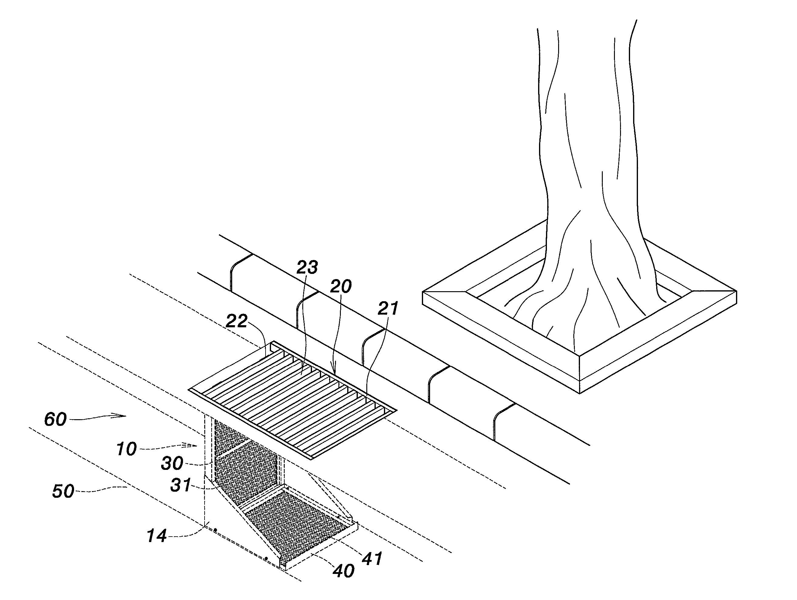
[0018] Referring to FIG. 3 through FIG. 8, various schematic views illustrate a drain garbage collector according to an embodiment of the present invention. The garbage collector comprises a frame 10, a top grate 20, a separator grate 30, and a collector grate 40. The frame 10 is L-shaped and made of metallic materials. First pivot connecting structures 11 are placed on the rear side edge of the frame 10 to connect the top grate 20 coaxially via pivot axles 12. The top grate 20 is made of metallic materials also, and is constituted of a plurality of bars 21 that are spaced apart from one another so as to define a plurality of passages 23 there between. The bars 21 may form the top grate 20 via various methods such as soldering, hard soldering, ultra-sonic welding, or resistive welding, etc.

[0019] Second pivot connecting structures 22, corr...


PUM


Abstract

A drain garbage collector of the invention includes a frame, a top grate, a separator grate, and a collector grate. A plurality of passages are defined through the top grate let the roadside garbage pass through. The separator grate prevents garbage from flowing out of the garbage collector via filtering wastewater flow. Thereby, the garbage collector collects garbage and the collected garbage can be cleaned regularly to prevent inundation caused by jammed drain.

Description

[0001] 1. Field of the Invention[0002] The invention relates to a drain garbage collector. More particularly, the invention provides a drain garbage collector that can effectively collect drain garbage while preventing inundation caused by garbage jam.[0003] 2. Description of the Related Art[0004] Referring to FIG. 1 and FIG. 2, two perspective views illustrate the structure of a conventional drain garbage collector disclosed in the Taiwan Patent No. 197035. The known garbage collector comprises a frame structure 1, a retainer basin 2, and a drain cover grate 3.[0005] The retainer basin 2 is mounted to the frame structure 1, and hence theassembled structure is covered by the drain cover grate 3 defining a plurality of holes 31 and placed within the drain, as shown as in FIG. 2, to collect roadside garbage. The above conventional drain garbage collector can therefore receive and contain garbage, but is not effective to filter flowing garbage in the drain itself.[0006] Moreover, if th...

Claims


Application Information

Patent Timeline
IPC IPC(8): E03F1/00
CPCE03F5/0404E03F1/00
Inventor TSENG, WEN CHING
Owner TSENG WEN CHING
Why Eureka
Try Eureka