

Fuel cell power generation system
a technology of power generation system and fuel cell, which is applied in the direction of fuel cells, electrochemical generators, electrical equipment, etc., can solve the problems of reducing power generation efficiency, difficult to have the various elements perform their functions well when using a compact package, and not easy to be affected by the hot portion during the operation of the system
- Summary
- Abstract
- Description
- Claims
- Application Information
AI Technical Summary
Benefits of technology
Problems solved by technology
Method used
Image


Examples
first embodiment
[0030] (First Embodiment)
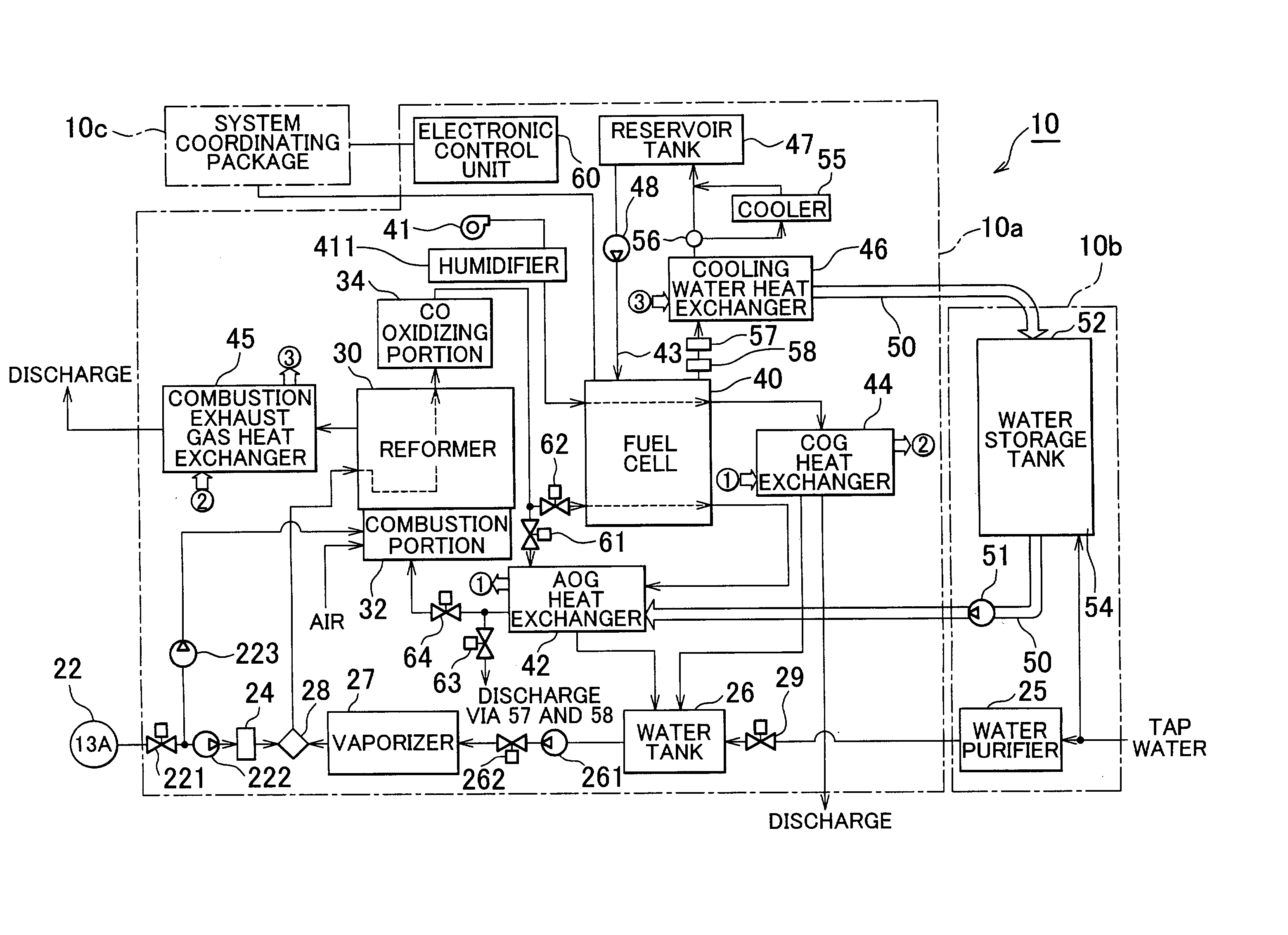
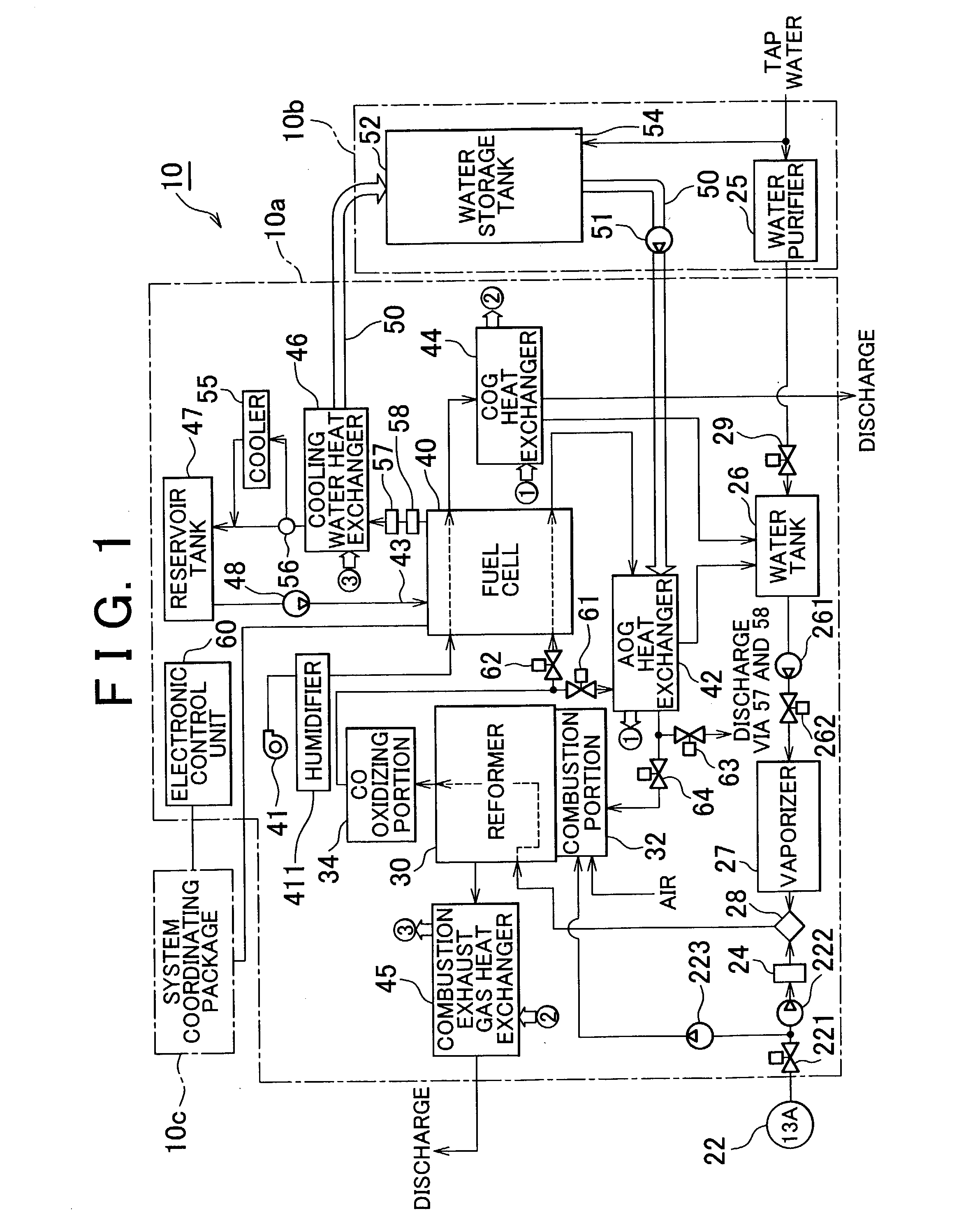
[0031] First, a first exemplary embodiment of the invention will be described with reference to the drawings. FIG. 1 is a block diagram schematically showing the structure of a fuel cell power generation system 10 according to the first exemplary embodiment of the invention. FIG. 2 is a block diagram showing signal inputs and outputs of an electronic control unit 60 of the fuel cell power generation system 10.
[0032] Referring to FIG. 1, the fuel cell power generation system 10 mainly includes a reformer 30 that reforms city gas into hydrogen rich reformate gas, a CO oxidizing portion 34 that reduces the carbon monoxide in the reformate gas so as to make it a fuel gas, a mixer 28 that mixes the city gas and vapor at an appropriate ratio and supplies the mixture to the reformer 30, a water tank 26 (also referred to as a "water recovery tank") that serves as a supply source for the vapor to be supplied to the mixer 28, a fuel cell 40 that generates power by an ...
second embodiment
[0061] (Second Embodiment)
[0062] Next, a second exemplary embodiment according to the invention will be described with reference to FIG. 5. FIG. 5 is a view corresponding to the block diagram schematically showing the configuration of the fuel cell power generation system of the foregoing first exemplary embodiment. Further, FIG. 5 also shows the vertical positional relationship between the various elements of the system. Also, to facilitate understanding, only the elements relating to the aim of the second exemplary embodiment are shown in the figure. Like elements in the first and second exemplary embodiments shall be denoted by like reference numerals.
[0063] Referring to FIG. 5, a fuel cell power generation system 110 according to the second exemplary embodiment includes a fuel cell 40 made up of a stack 400 in which a multiplicity of fuel cell cells 410 are stacked together, a condenser 142 (equivalent to the anode off gas heat exchanger 42 in the first exemplary embodiment) and...
third embodiment
[0081] (Third Embodiment)
[0082] Next, a third exemplary embodiment will be described. The third exemplary embodiment differs from the second exemplary embodiment only in that the position of the members is different and some of the members are replaced with other members. Those members in the third exemplary embodiment that are substantially the same as the members in the second exemplary embodiment shall be denoted by like reference numerals, and descriptions of those members shall be omitted.
[0083] Referring to FIG. 6, the reformer 30 is disposed to the side of the stack 400. Communication is provided between the reformer 30 and a moisture removal device 135 by a pipe 302. Midway in the pipe 302 at a point close to the moisture removal device 135, a pipe 361 branches off from the pipe 302 so as to provide communication with the stack 400. The moisture removal device 135 is structured substantially similar to the moisture removal device 35 in the second exemplary embodiment.
[0084] ...
PUM
 Abstract
Description
Claims
Application Information