Method and device for controlling the drive unit of a motor vehicle

a technology for driving units and motor vehicles, applied in the direction of electric control, speed sensing governors, machines/engines, etc., can solve the problems of particularly active limiters, achieve the effect of avoiding loss and comfort, soft transition into the operating range of limiters, and improve comfor

Inactive Publication Date: 2003-08-14
ROBERT BOSCH GMBH
View PDF10 Cites 2 Cited by
  • Summary
  • Abstract
  • Description
  • Claims
  • Application Information

AI Technical Summary

Benefits of technology

0005] The described measures improve the comfort as well as the effect of the limiter. It is especially advantageous that the interrelationship of the limiter with other functions of the engine control is considered. In this way, it is ensured that the limiter and the idle controller and / or the limiter and the travel comfort functions (for example, dashpot function, load impact damping, jolt damping, et cetera) do not operate against each other, and in this way, affect the driving comfort or the action of the limiter.
0006] In an especially advantageous manner, the integrator, which is used in the limiter, is limited. In a preferred embodiment, a limit value which is below the negative value of the input value for a control variable of the drive unit (for example, the torque desired value) is used. In this way, it is ensured that this input value can never be less than zero. The generation of a negative torque of the drive unit (braking operation) for an active limiter and the loss and comfort associated therewith is effectively avoided.
0007] It is also advantageous that the limiter is only active when at least one present driving comfort function is ended. In combination with a function, which smoothes (dashpot function) the transition when releasing the accelerator pedal, it is avoided that the limiter suddenly limits the engine torque when the driver releases the foot from the accelerator pedal with the clutch engaged and at high speed so that a soft transition into the operating range of the limiter is ensured.
0008] A further advantageous improvement is in the use of a controlled integrator in lieu of a PID controller for limiting rpm. The advantage is that one can pregive the operation of the integrator in dependence upon the operating state of the system (rising, falling, constant) and, in this way, preventing vibration which can occur because of the interaction of the integrators of the rpm limiter and the idle controller.
0009] Furthermore, it is advantageous that a decoupling of the effective ranges of idle controller and limiter is provided by means of an rpm-dependent characteristic line. With the weighting of the output signal of the limiter in dependence upon the rpm, the effect of the limiter is reduced or disabled in rpm regions wherein, as a rule, the idle controller operates for maintaining the desired idle rpm. In rpm regions, which lie close to the monitoring rpm, the limiter is permitted to be fully effective. In this way, the function ranges of both functions are essentially decoupled so that they do not mutually disadvantageously affect each other.
0010] With the improvements, the advantages of the monitoring rpm limiter are maintained in an advantageous manner. The advantages of the monitoring rpm limiter are: the independence of scattering of individual engines, the service life of the engine and the ambient conditions (temperature, elevation above sea level, et cetera) which are present in each case. The limiter reduces the complexity of application because not each characteristic value need be considered in the monitoring. The characteristic variable operates to increase torque as may be required in the case of a fault. For this reason, the development process is simplified because the introduction of new characteristic variables is simplified which need not be considered in the monitoring. Furthermore, the use of the limiter is independent of the type of control system; for example, this is so whether the system is a system having intake manifold injection, a system with gasoline direct injection, a control system for a diesel engine or for an alternative drive concept (electric motor, et cetera).

Problems solved by technology

This limiting is especially active when the accelerator pedal is not depressed.

Method used


Image

  • Method and device for controlling the drive unit of a motor vehicle
  • Method and device for controlling the drive unit of a motor vehicle
  • Method and device for controlling the drive unit of a motor vehicle

Examples


Embodiment Construction

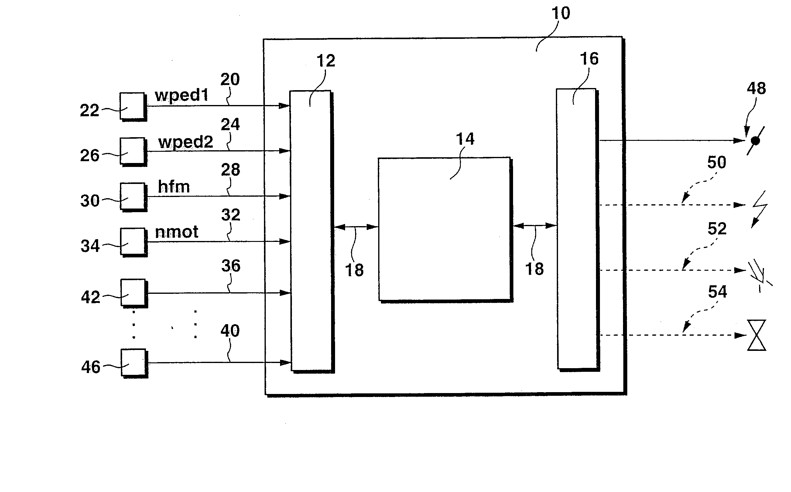
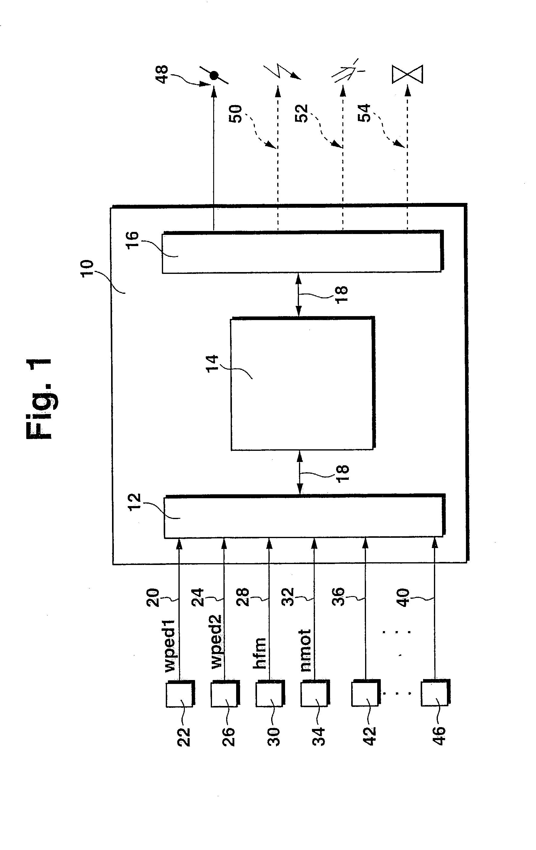
[0016] FIG. 1 shows an electronic control unit 10 which includes at least an input circuit 12, at least one microcomputer 14 and at least an output circuit 16. Input circuit, microcomputer and output circuit are connected to each other for mutual data exchange via a communications system 18. The following input lines lead to the input circuit 12: an input line 20 from a measuring device 22 for detecting the accelerator pedal position wped; an input line 24 from a measuring device 26 for detecting the throttle flap position wdk; an input line 28 from a measuring device 30 for detecting the air mass hfm, which is supplied to the engine; an input line 32 from a measuring device 34 for detecting the engine rpm nmot; and, input lines 36 to 40 from measuring devices 42 to 46 for detecting additional operating variables of the engine and / or of the vehicle which are needed for carrying out the engine control or from which such operating variables are derived such as intake air temperature, ...


PUM


Abstract

A method and arrangement for controlling the drive unit of a vehicle is suggested wherein a limiter is provided to limit the engine rpm to a pregiven limit value in at least one operating state. The limiter is controlled to be ineffective in this at least one operating state in dependence upon at least one additional operating variable.

Description

STATE OF THE ART[0001] The invention relates to a method and an arrangement for controlling the drive unit of a vehicle.[0002] From DE-A 195 36 038, a method and an arrangement for controlling an internal combustion engine is known wherein a maximum permissible torque is formed for ensuring the operational reliability of the engine control. This maximum permissible torque is formed at least on the basis of the position of an operator-controlled element actuable by the driver. This maximum permissible torque is compared to an actual torque of the engine. If the actual torque exceeds the maximum permissible torque, then it is assumed that there is a defective function of the control and measures are initiated to react to the fault until the actual torque again drops under the maximum permissible torque. This torque monitoring is greatly dependent upon the quality of the detection of the actual torque. To improve the monitoring of the control of the engine, there was a supplement made ...

Claims


Application Information

Patent Timeline
Patent Type & Authority Applications(United States)
IPC IPC(8): F02D45/00F02D31/00F02D41/08F02D41/12F02D41/22
CPCF02D31/006F02D31/009Y02T10/40F02D2250/18F02D41/22F02D31/00
Inventor KUSTOSCH, MARIO
Owner ROBERT BOSCH GMBH
Why Eureka
Try Eureka