Apparatus and method for sensing spatial displacement in a heart

a technology of spatial displacement and apparatus, applied in the field of apparatus and method for sensing spatial displacement in the heart, can solve the problems of insufficient information, transmission of defibrillating shock, and difficulty in determining by using traditional methods whether

Inactive Publication Date: 2003-08-21
MEDTRONIC INC
View PDF5 Cites 50 Cited by
  • Summary
  • Abstract
  • Description
  • Claims
  • Application Information

AI Technical Summary

Problems solved by technology

Further, if fibrillation is detected in a portion of the heart, a defibrillating shock may be transmitted to that part of the heart that is experiencing fibrillation.
For example, merely sensing that the heart is beating electrically may not provide sufficient information to determine whether the left ventricle is contracting, and thus outputting blood, a commens

Method used


Image

  • Apparatus and method for sensing spatial displacement in a heart
  • Apparatus and method for sensing spatial displacement in a heart
  • Apparatus and method for sensing spatial displacement in a heart

Examples


first embodiment

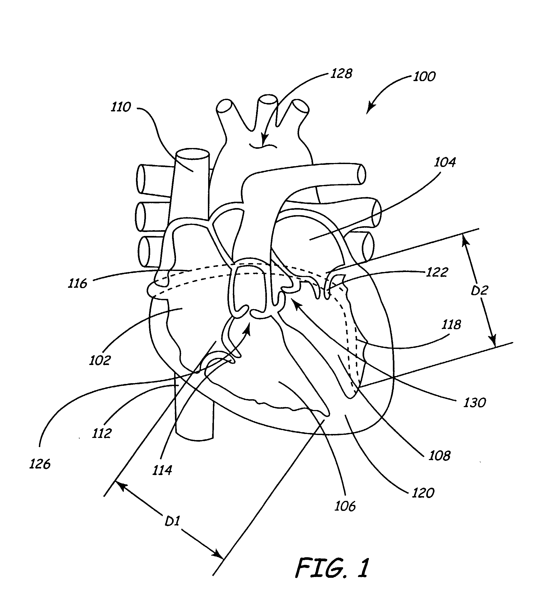
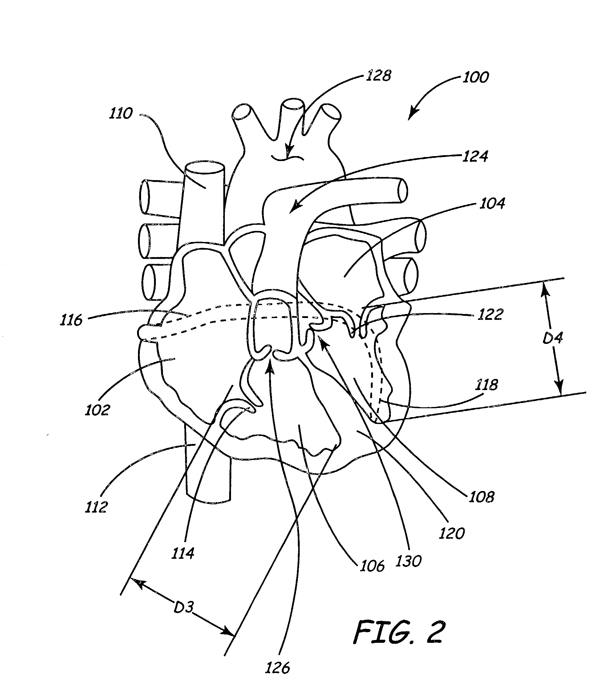
[0035] FIGS. 5 and 6 illustrate the leads 302, 304 according to the present invention in which each of the leads 302, 304 includes one or more sensing elements 502 capable of sensing bending stress induced in the leads 302, 304. In one embodiment, the bending stress induced in the leads 302, 304 may be caused by changes in dimensions (e.g., D.sub.1, D.sub.2, D.sub.3, D.sub.4, or the like) as the heart 100 beats. In the embodiment illustrated in FIG. 6, the sensing element 502 includes a plurality of strain gauges 602 mounted to a substrate 604. While three strain gauges 602 are illustrated in FIG. 6, the use of any desired number or configuration of strain gauges 602 is encompassed by the present invention. Conductors 606 may originate from the strain gauges 602 to electrically couple the strain gauges 602 and the control unit 306 (shown in FIGS. 3 and 4) and, further, to provide electrical power to the strain gauges 602. The leads 302, 304 flex as the heart 100 beats, causing chang...

second embodiment

[0036] FIGS. 5 and 7 illustrate the leads 302, 304 according to the present invention, in which each of the leads 302, 304 includes one or more sensing elements 502 capable of sensing bending stress induced in the leads 302, 304. In one embodiment, the bending stress induced in the leads 302, 304 may be caused by changes in dimensions (e.g., D.sub.1, D.sub.2, D.sub.3, D.sub.4, or the like) as the heart 100 beats. In the embodiment illustrated in FIG. 7, the sensing element 502 includes one or more piezoresistive elements 702 mounted to a substrate 704. While one piezoresistive element 702 is illustrated in FIG. 7, the use of any desired number or configuration of piezoresistive elements 702 is encompassed by the present invention. Conductors 706 may originate from the piezoresistive element 702 to electrically couple the piezoresistive element 702 and the control unit 306 (shown in FIGS. 3 and 4) and, further, to provide electrical power to the piezoresistive element 702. The leads ...

third embodiment

[0037] the leads 302, 304 according to the present invention is illustrated in FIG. 8. The leads 302, 304 include a sensing unit 800 having a first ultrasonic element 802 that is disposed proximate an end portion 804 of the lead. The sensing unit 800 further includes a second ultrasonic element 808 that is disposed intermediate the first ultrasonic element 802 and the control unit 306 (shown in FIGS. 3 and 4). In one embodiment, the first ultrasonic element 802 emits ultrasonic energy, which may be transmitted through the heart 100 towards, and received by, the second ultrasonic element 808. Alternatively, the second ultrasonic element 808 emits ultrasonic energy, which may be transmitted through the heart 100 towards, and received by, the first ultrasonic element 802. One or more conductors 810 extend from each of the first ultrasonic element 802 and the second ultrasonic element 808 to electrically couple the ultrasonic elements 802, 808 with the control unit 306 to provide power ...


PUM


Abstract

An electrical lead includes an elongate body having a proximal end, and a sensing unit capable of resolving a change in a spatial configuration of the electrical lead. A medical device includes a control unit, an elongate body having a proximal end coupled with the control unit, and a sensing unit capable of resolving a change in a spatial configuration of the electrical lead and relating it to the amount of blood ejected from the heart. A method includes receiving a signal transmitted from a lead disposed within a heart and determining a change in a dimension of the heart, due to the heart beating, based upon the signal.

Description

[0001] This invention relates to a method and apparatus for sensing one or more spatial displacements in a heart.DESCRIPTION OF THE RELATED ART[0002] Methods have been developed over the years to monitor the heart's function and to deliver various stimuli thereto. For example, cardiac pacing systems may monitor the heart's rhythm by sensing electrical signals transmitted by cardiac nerves to the heart and propagates throughout the heart muscle. If, for example, the heart fails to beat for a predetermined period of time, a pacing signal may be transmitted to a portion of the heart. Further, if fibrillation is detected in a portion of the heart, a defibrillating shock may be transmitted to that part of the heart that is experiencing fibrillation.[0003] Sensing the electrical signals transmitted by the cardiac nerves and which propagates through the heart muscle generally provides an indirect indication, rather than a direct indication, of the mechanical function of the heart. For exam...

Claims


Application Information

Patent Timeline
IPC IPC(8): A61B5/11A61B5/107A61B8/08A61B8/12A61N1/05A61N1/08A61N1/365A61N1/39
CPCA61B5/1076A61N1/08A61N1/056A61B8/12
Inventor DAHL, ROGERKALLOK, MICHAEL J.SUNDQUIST, STEVE
Owner MEDTRONIC INC
Why Eureka
Try Eureka