Wireless communication system for multi-hop connection, source station, radio station and pilot signal used therein

a multi-hop connection and wireless communication technology, applied in the field of wireless communication systems for multi-hop connections, can solve the problems of lowering the area coverage, reducing the system capacity, and increasing the interference noise generated by the relay station relaying the signal

Inactive Publication Date: 2003-09-04
NTT DOCOMO INC
View PDF9 Cites 54 Cited by
  • Summary
  • Abstract
  • Description
  • Claims
  • Application Information

AI Technical Summary

Benefits of technology

[0011] In the present invention, the transmission path having the minimum total of the required transmission power values of the respective stations on the transmission path is selected among the candidates of the transmission path of the signal from the source station to the destination station, and the pilot signal including the identification information about the respective stations on this selected transmission path and the required transmission power values thereof is transmitted to the source station and the relay station. Thus, the destination station and the relay station, which have received the pilot signal, can determine the transmission path having the minimum total of the required transmission power values by use of the identification information included in the received pilot signal in the signal transmission performed threreafter and can transmit the signal with the respective required transmission powers by use of the required transmission power values included in the received pilot signal. As a result, the total of the required transmission power values in transmitting the signal from the source station to the destination station can be minimized, the increase of the interference noise generated in relaying of the signal transmission by the relay station can be suppressed, and the increase of the system capacity and the area coverage can be achieved.
[0014] The destination station specifies the transmission path from the source station to the destination station by use of the identification information included in the received pilot signal and selects the transmission path having the minimum total of the required transmission power values among the candidates of the transmission path. In such a manner, a part of processing necessary for the selection of the transmission path is performed also by the relay station, and thus a load of the processing in the destination station is reduced. Note that, also as to the transmission path from the source station to the destination station, the direct transmission path going through no relay station and the transmission path going through one or more relay stations may be possible.

Problems solved by technology

In this single-hope connection method, if a maximum transmission power in the source station is prescribed, large propagation loss and interference noise power make it impossible to establish the wireless link between the source station and the destination station, thereby resulting in lowering of an area coverage.
However, when the multi-hop connection method is applied to CDMA (Code Division Multiple Access), it is conceivable that, compared to the TDMA and CSMA, new interference noise generated when the relay stations relay the signal is increased.
Thus, it is concerned that the increased interference noise becomes a factor that lowers a system capacity.

Method used


Image

  • Wireless communication system for multi-hop connection, source station, radio station and pilot signal used therein
  • Wireless communication system for multi-hop connection, source station, radio station and pilot signal used therein
  • Wireless communication system for multi-hop connection, source station, radio station and pilot signal used therein

Examples


Embodiment Construction

[0042] With reference to the drawings, an embodiment of the present invention will be described below.

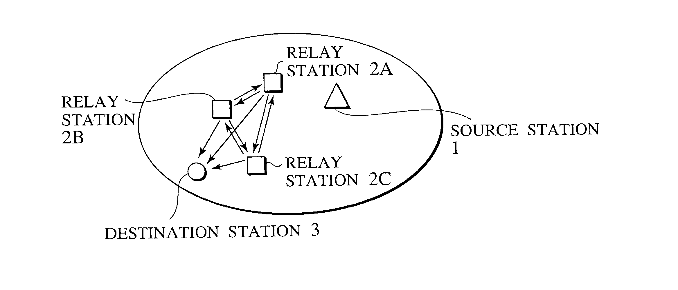
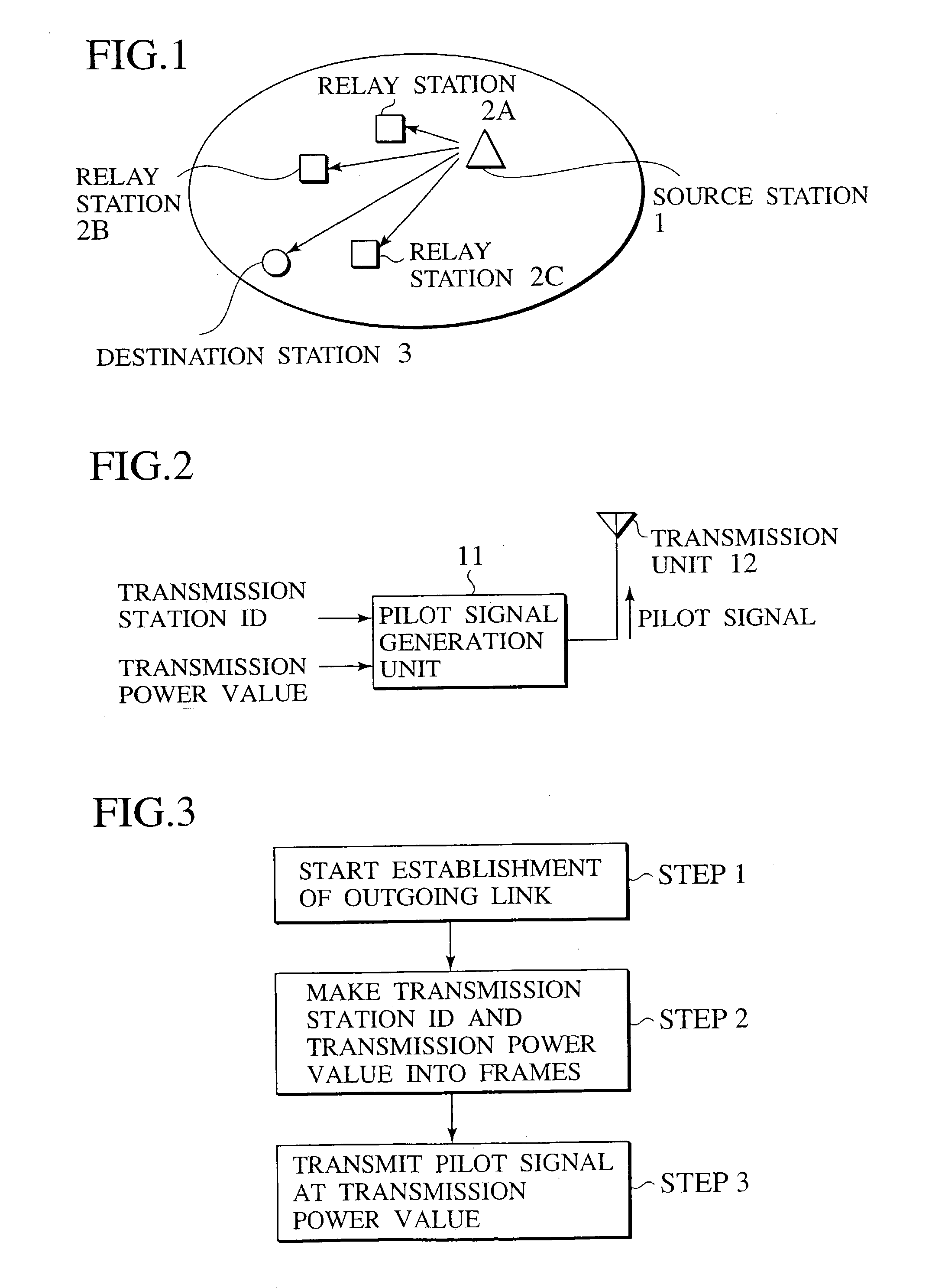
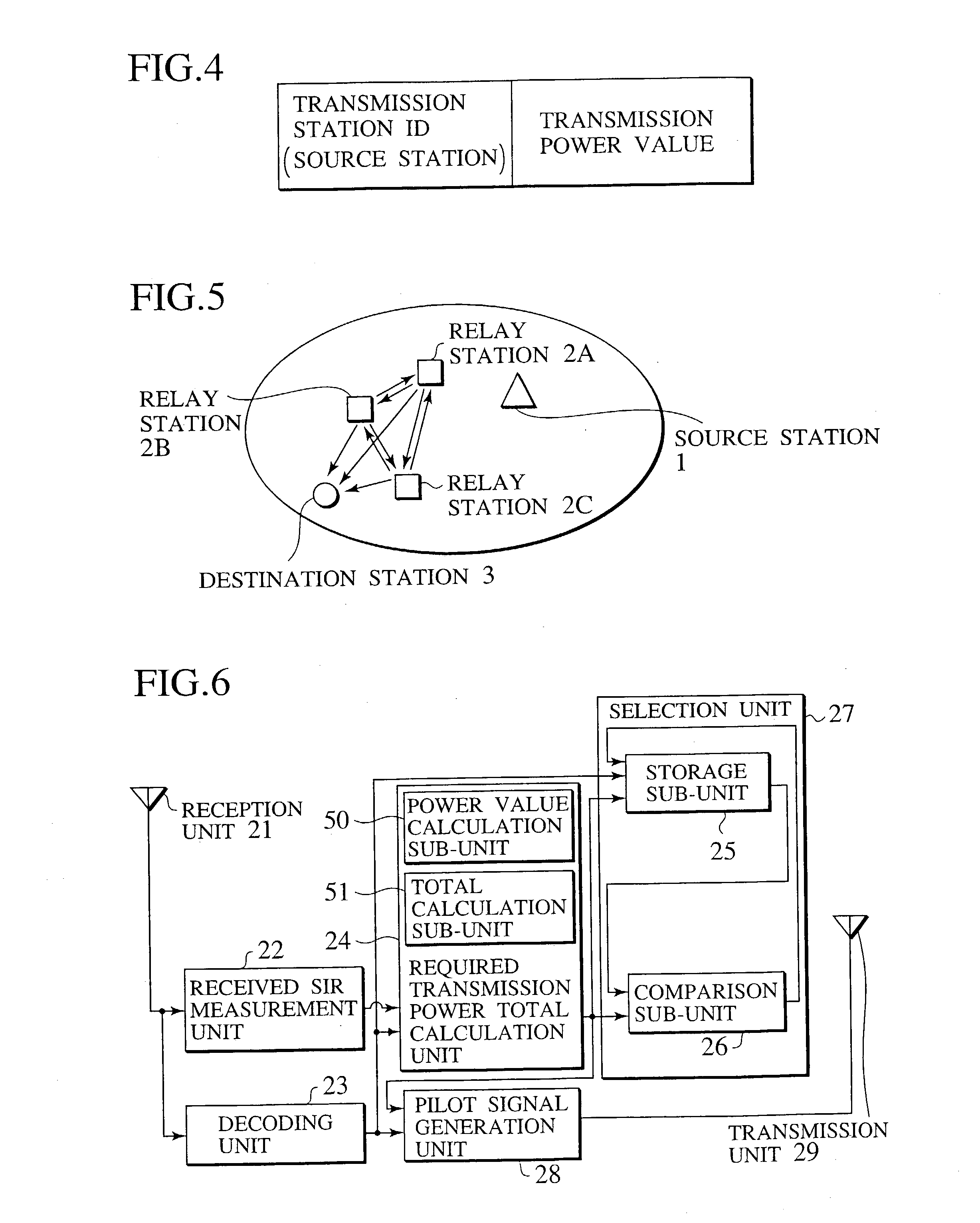
[0043] FIG. 1 is a block diagram showing a general schematic constitution of a wireless communication system for a multi-hop connection according to one embodiment. The wireless communication system of FIG. 1 is constituted of a source station 1, a plurality of relay stations 2 (which are appropriately denoted as "relay stations 2A, 2B, 2C . . . " for the respective relay stations) and a destination station 3. The respective relay stations 2A, 2B and 2C have basically a similar constitution. As to a transmission path of a signal from the source station 1 to the destination station 3, there are a transmission path in which the signal is directly transmitted from the source station 1 to the destination station 3 and a transmission path in which the signal is transmitted by being relayed through one or more of the relay stations 2 before reaching the destination station 3 from the sour...


PUM


Abstract

A destination station 3 in a wireless communication system for a multi-hop connection selects a transmission path having a minimum total of required transmission power values of respective stations on the transmission path among candidates of the transmission path from a source station 1 to the destination station 3 and transmits a pilot signal to the source station 1 and a relay station 2, the pilot signal including identification information about the respective stations on the selected transmission path and required transmission power values thereof. Thus, the source station 1 and the relay station 2, which have received this pilot signal, can determine the transmission path having the minimum total of the required transmission power values by use of the identification information included in the received pilot signal.

Description

[0001] This application is based upon and claims the benefit of priority from Japanese Patent Application No. 2002-56557 filed Mar. 1, 2002; the entire contents of which are incorporated herein by reference.[0002] 1. Field of the Invention[0003] The present invention relates to a wireless communication system for a multi-hop connection, in which a signal is transmitted between a source station, a plurality of relay stations and a destination station, and to the source station, relay stations, destination station and a pilot signal, all of which are used therein.[0004] 2. Description of Related Art[0005] As the wireless communication system, a system using a single-hop connection method is known. Specifically, in the single-hop connection method, a station to be a source of transmitting a signal (hereinafter referred to as a "source station") establishes a wireless link directly to a station as a destination of the transmission (hereinafter referred to as a "destination station"), th...

Claims


Application Information

Patent Timeline
Patent Type & Authority Applications(United States)
IPC IPC(8): H04B7/24H04B7/15H04W16/26H04W40/00H04W40/08H04W40/16H04W40/24H04W88/04
CPCH04L45/00H04W40/00H04W88/04H04W40/16H04W40/246H04W40/08Y02D30/70H04B1/76
Inventor FUJIWARA, ATSUSHITAKEDA, SHINJIYOSHINO, HITOSHIOTSU, TORU
Owner NTT DOCOMO INC
Why Eureka
Try Eureka