Numerical controlling unit having tool-breakage detecting function

a technology of numerical control unit and tool, applied in the direction of electrical programme control, program control, instruments, etc., can solve the problems of tool breakage, tool breakage cannot be detected, and it is difficult to detect tool breakage by a single reference value,

Inactive Publication Date: 2003-09-04
TOSHIBA MASCH CO LTD
View PDF13 Cites 15 Cited by
  • Summary
  • Abstract
  • Description
  • Claims
  • Application Information

AI Technical Summary

Benefits of technology

[0013] According to the present invention, a load change caused by a breakage of a tool can be more sensitively detected. Thus, even in a step of machining a mold wherein a load change is great, a breakage of a tool can be more accurately detected. The term "a breakage of a tool" includes a breakage of a cutting edge of the tool as well as an excessively abraded state of a cutting edge of the tool.

Problems solved by technology

Therefore, when a tool breaks at a cutting step of a lower load, there is the possibility that the tool breakage cannot be detected, because the load torque value does not become higher than the reference value.
In machining a mold, since a load changes greatly, it is difficult to detect a tool breakage by a method in which a single reference value is set per tool.
The term "a breakage of a tool" includes a breakage of a cutting edge of the tool as well as an excessively abraded state of a cutting edge of the tool.

Method used


Image

  • Numerical controlling unit having tool-breakage detecting function
  • Numerical controlling unit having tool-breakage detecting function
  • Numerical controlling unit having tool-breakage detecting function

Examples


Embodiment Construction

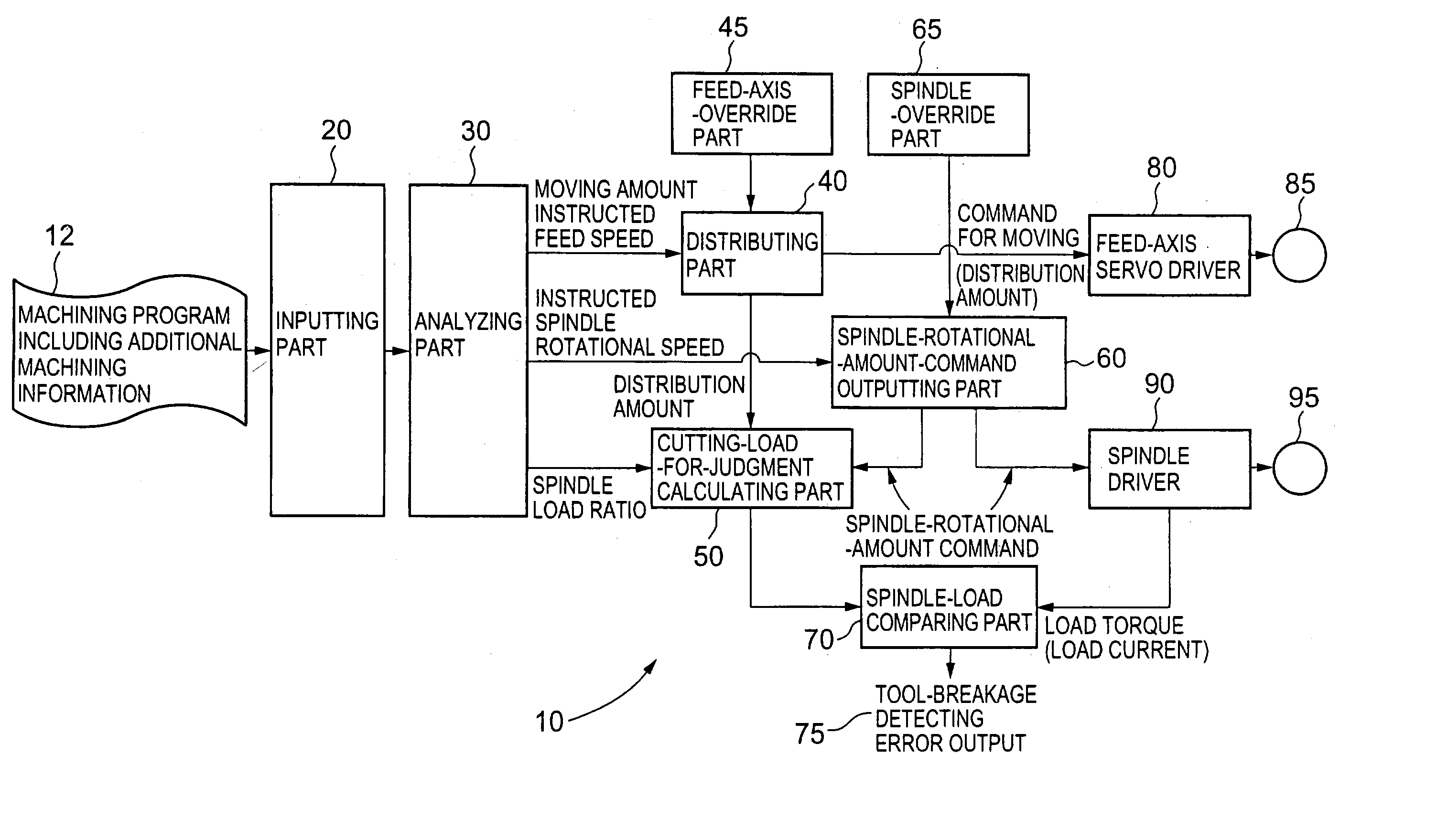
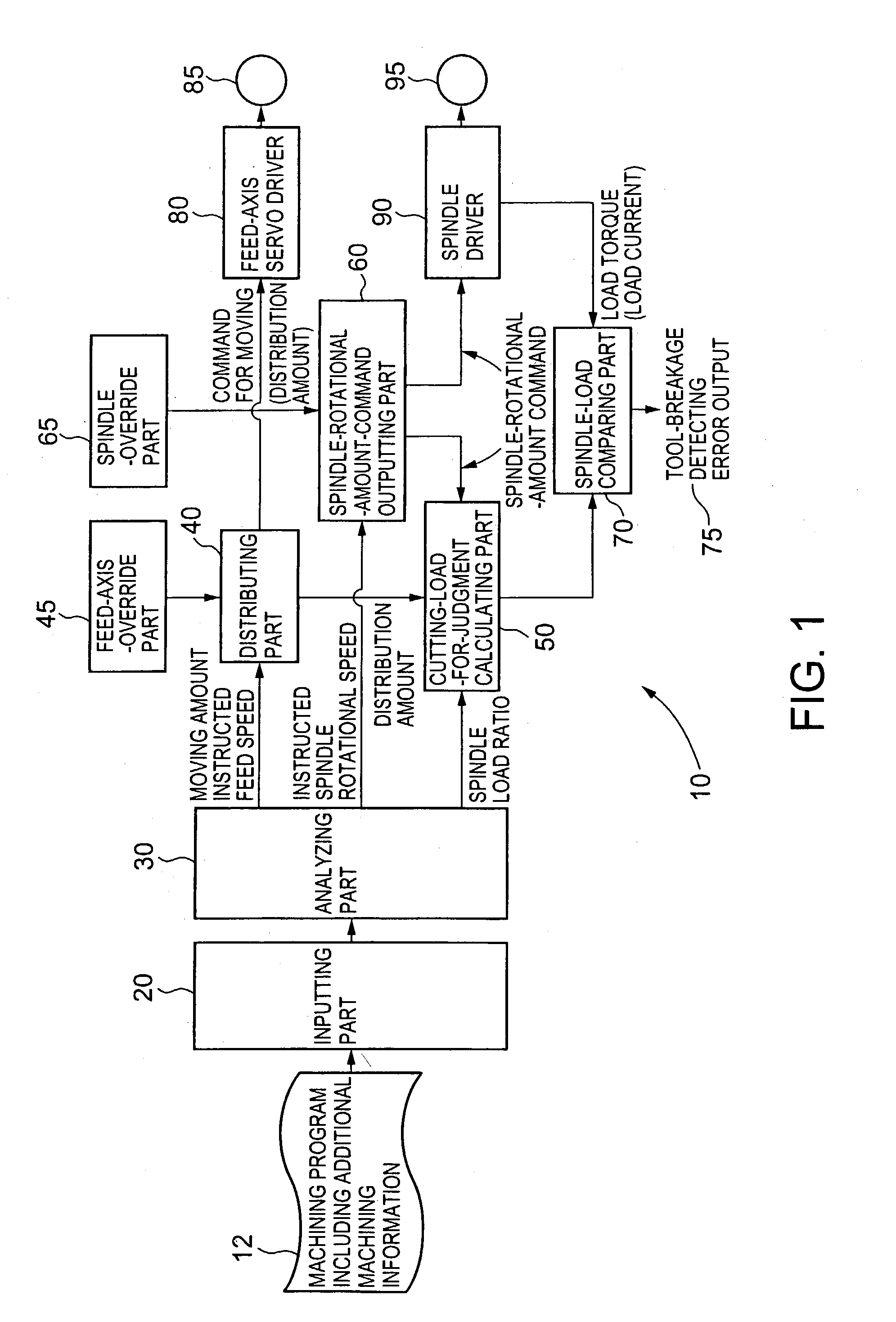
[0019] An embodiment of the present invention is described below with reference to FIG. 1. FIG. 1 is a block diagram showing an embodiment of a numerical controlling unit according to the present invention, relating to a tool-breakage detection. The numerical controlling unit 10 includes block components of an inputting part 20, an analyzing part 30, a distributing part 40, a feed-axis-override part 45, a cutting-load-for-judgment calculating part 50, a spindle-rotational-amoun-t-command outputting part 60, a spindle-override part 65, a spindle-load comparing part 70, a feed-axis servo driver 80, a feed-axis servomotor 85, a spindle driver 90, and a spindle motor 95.

[0020] Each of the above block components is described below.

[0021] A machining program 12 instructed for machining a workpiece is inputted into the inputting part 20. The machining program 12 includes a feed speed indicating a relative speed between the workpiece and a tool, and additional machining information relating...


PUM

PropertyMeasurementUnit
speedaaaaaaaaaa
rotational speedaaaaaaaaaa
torqueaaaaaaaaaa

Abstract

A numerical controlling unit according to the present invention includes: an inputting part into which a machining program for machining a workpiece is inputted; an analyzing part that analyzes the machining program to generate an instructed spindle rotational speed and calculates a spindle load ratio indicating a ratio of a load applied to a spindle under a machining condition according to the machining program, with respect to a spindle load being caused when the workpiece is machined under a machining condition of a certain reference; and a distributing part that generates, based on the machining program, a distribution amount per unit period to be inputted into a feed-axis servo driver for moving a feed axis. A spindle-rotational-amount-command outputting part receives the instructed spindle rotational speed and outputs a spindle-rotational-amount command for commanding a rotational amount per unit period. The spindle-rotational-amount command is inputted into a spindle driver. A cutting-load-for judgment calculating part calculates a reference torque value based on the spindle load ratio outputted by the analyzing part, the distribution amount outputted by the distributing part, and the spindle-rotational-amount command outputted by the spindle-rotational-amount-command outputting part. A spindle-load comparing part compares the reference torque value with a load torque value which is feedback inputted by the spindle driver and outputs a tool-breakage detecting signal when the load torque value is higher than the reference torque value.

Description

[0001] 1. Field of the Invention[0002] The present invention relates to a numerical controlling unit having a highly accurate tool-breakage detecting function.[0003] 2. Description of Related Art[0004] A tool such as a drill is generally attached to a spindle. The tool is rotated by rotating the spindle so that a workpiece is cut by means of a relative speed between the spindle and the workpiece. The spindle is driven in rotation by a rotation of a spindle motor. Thus, when cutting a workpiece, a load caused by the cutting is indicated as an electric current of the servomotor.[0005] If a tool, in particular a cutting edge of a tool, breaks or fails during cutting, a load caused by the cutting is changed, and thus a current of the servomotor is changed. By previously setting a current value indicating a load at a breakage of the tool (cutting edge of the tool) as a reference value, and monitoring the current value of the servomotor which drives a spindle, a tool breakage can be detec...

Claims


Application Information

Patent Timeline
Patent Type & Authority Applications(United States)
IPC IPC(8): G05B19/4065
CPCG05B19/4065Y10T408/165Y10T408/14G05B2219/37246G05B19/18
Inventor FUJITA, JUNMATSUMOTO, ICHIRO
Owner TOSHIBA MASCH CO LTD
Why Eureka
Try Eureka